Broadcasting signal receiving system

a technology of receiving system and broadcasting signal, which is applied in the field of broadcasting signal receiving system, can solve the problems of confusion and inability to differentiate between individual persons having different personal characteristics, and achieve the effect of preventing careless operation by another viewer and suppressing unnecessary power consumption

Inactive Publication Date: 2006-08-24
FUNAI ELECTRIC CO LTD
View PDF8 Cites 41 Cited by
  • Summary
  • Abstract
  • Description
  • Claims
  • Application Information

AI Technical Summary

Benefits of technology

[0022] According to the third-aspect, when it is determined by the opened / closed state determining unit that the eyes are closed for a predetermined time or more, the recording reproducing control unit records a recording position of a corresponding time, and makes a receiving program continuously recorded by the recording reproducing unit in the common recording state. In addition, when it is determined by the opened / closed state determining unit that the eyes are opened again and it is determined that the detected person is the same person as the first person based on the recognized result by the recognition unit, the recording reproducing control unit makes the recorded program return to the recording position so as to be reproduced. That is, when the viewer is sleeping, the program is continually recorded, and when the viewer is wake up, the recorded program returns to the recording position. Therefore, the viewer can make scenes missed when the viewer is sleeping reproduced so as to view the missed scenes.
[0023] In this case, when it is determined by the opened / closed state determining unit that the eyes are closed for a predetermined time or more, the recording reproducing control unit changes an operation mode of the broadcasting signal receiving system from a common mode to a power saving mode at a corresponding time, and when it is determined by the opened / closed state determining unit that the eyes are opened again, the recording reproducing control unit makes an operation mode of the broadcasting signal receiving system return to the common mode from the power saving mode at a corresponding time. Thereby, it is possible to suppress the unnecessary power consumption.
[0024] According to the above-aspect, the broadcasting signal receiving system may further include a notification unit that notifies the viewer that automatic recording is being recorded, when it is determined that the eyes are opened again by the opened / closed state determining unit and it is recognized that the detected person is different from the first person based on the recognition result by the recognition unit in a common recording state in which the simple recording function becomes invalid. By adopting this structure, careless operation by a different person, that is, operation such as stopping automatic recording can be prevented in advance. For example, when another viewer comes in front of the television in a state in which the first viewer falls fast asleep, the above-mentioned situation is generated. However, according to this aspect, the careless operation by another viewer can be prevented in advance.
[0025] According to the above-aspect, in a common recording state in which the simple recording function becomes invalid, when it is determined by the opened / closed state determining unit that the eyes are opened again and it is determined that the detected person is different from the first person based on the recognition result of the recognition unit, the recording reproducing control unit makes operation input by the different person invalid and displays a warning message indicating that the input is invalid on a screen while maintaining the common recording state. By adopting this structure, careless operation by a different person, that is, operation such as stopping automatic recording can be prevented in advance.

Problems solved by technology

Therefore, it is not possible to differentiate between each individual person having different personal characteristics.
Therefore, since all the missed scenes cannot be reproduced, the father may feel confusion.

Method used


Image

  • Broadcasting signal receiving system
  • Broadcasting signal receiving system
  • Broadcasting signal receiving system

Examples


first embodiment

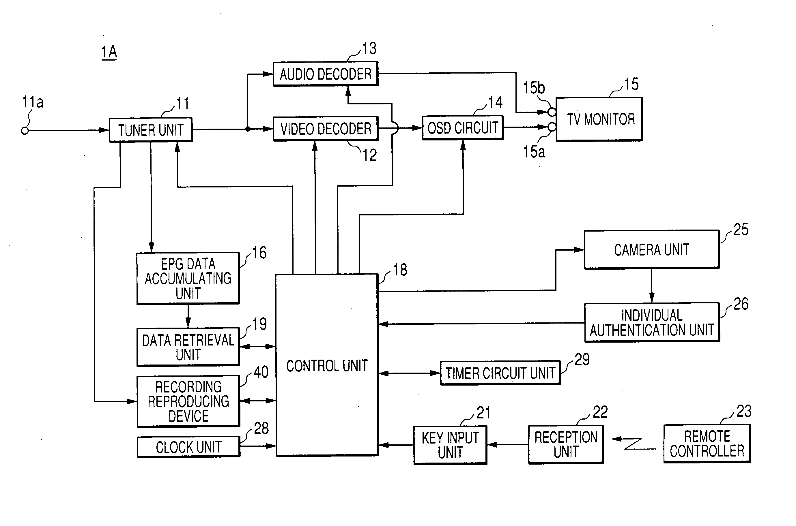
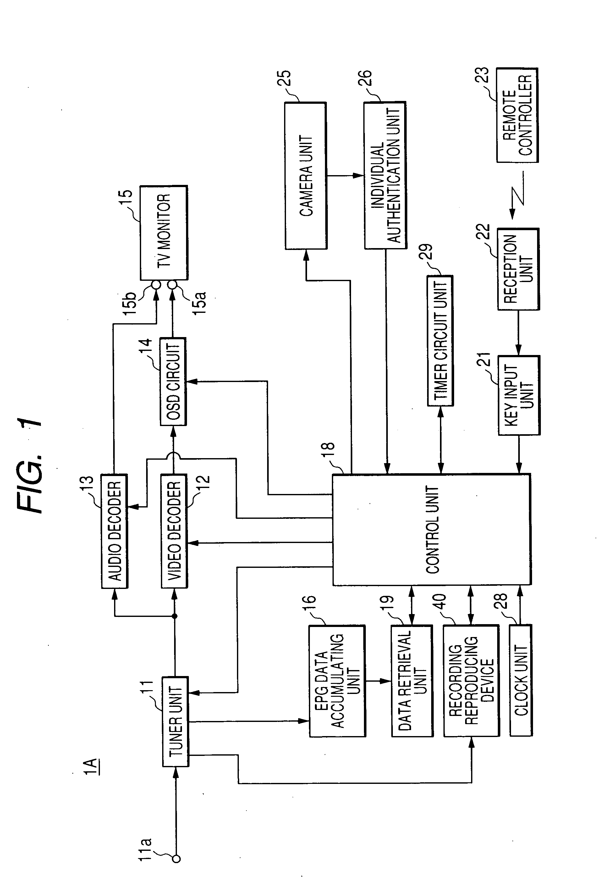
[0050]FIG. 1 is a functional block diagram illustrating an entire structure of a broadcasting signal receiving system according to a first embodiment of the invention.

[0051] A broadcasting signal receiving system 1A has an input terminal 11a that inputs a broadcasting signal received by an antenna (not shown). The input terminal 11a is connected to a tuner unit 11. An output terminal of the tuner unit 11 is connected to a video decoder 12 that coverts a digital video signal into an analog video signal. In addition, the output terminal of the tuner unit 11 is connected to an audio decoder 13 that converts a digital audio signal into an analog audio signal. Further, an output terminal of the video decoder 12 is connected to a video input terminal 15a of a TV monitor 15 through an OSD (on-screen display) circuit 14. Furthermore, an output terminal of the audio decoder 13 is connected to an audio input terminal 15b of the TV monitor 15.

[0052] Further, the output terminal of the tuner ...

example 1

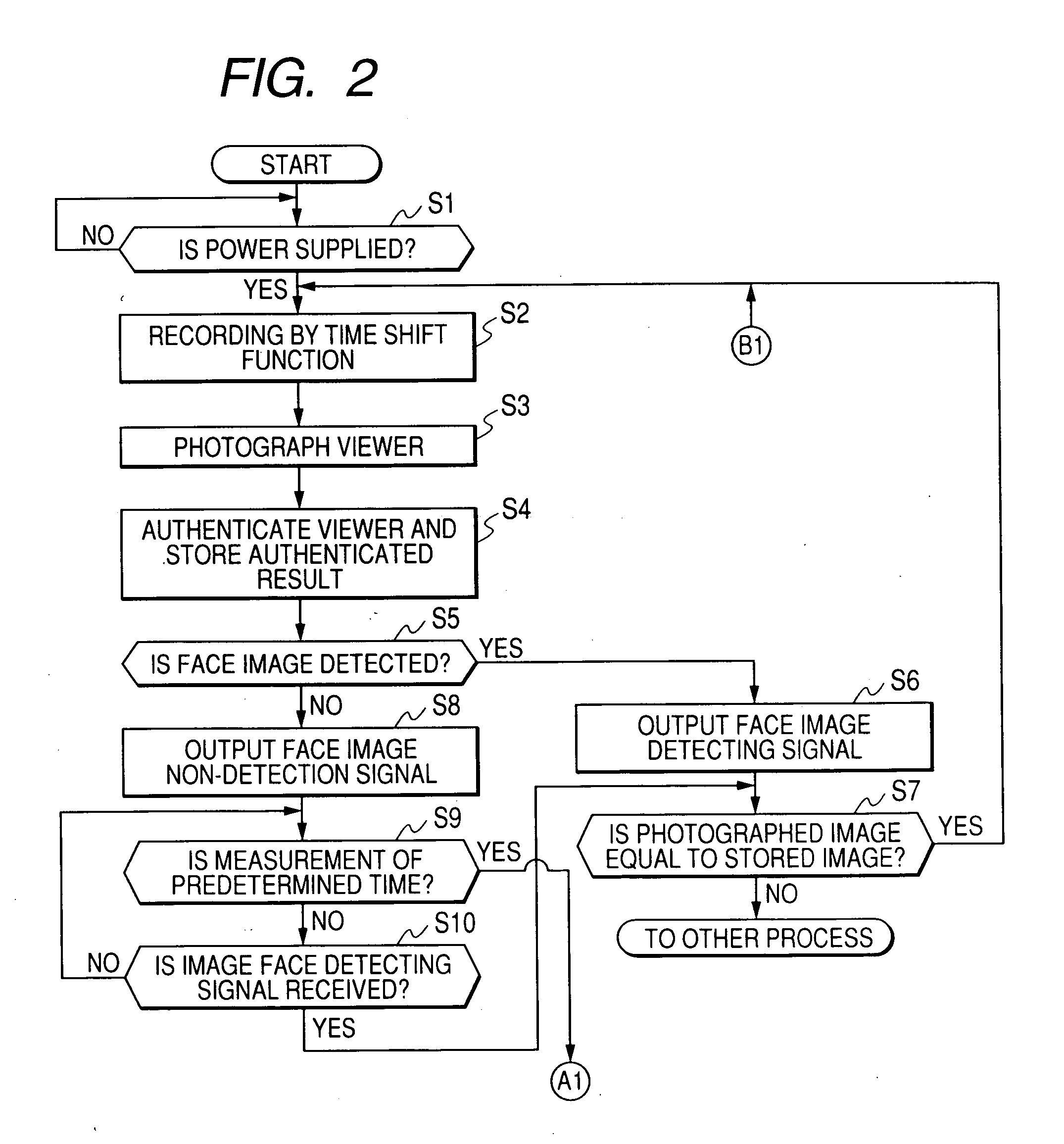
[0062]FIGS. 2 and 3 are flowcharts illustrating an automatic recording producing process according to Example 1. The Example 1 corresponds to a case in which the viewer leaves the front of a television receiver and then returns to the front of the television receiver again.

[0063] For example, if the television is turned on by means of the remote controller 23 (if determined as Yes in step S1), the control unit 18 starts recording by a time shift function (step S2), displays a program of a received channel on a screen of a TV monitor 15, and controls the camera unit 25 so as to start to photograph the viewer (step S3).

[0064] The individual authentication unit 26 compares features of a face image of the viewer photographed by the camera unit 25 with features of each of the family stored in the internal memory in advance so as to authenticate (specify) the corresponding viewer, and stores the authenticated result (features of a face image of a specific person who is currently viewing...

example 2

[0073]FIGS. 4 and 5 are flowcharts illustrating an automatic recording reproducing process according to Example 2. Example 2 corresponds to a case in which the viewer is sleeping in front of the television receiver.

[0074] For example, if the television is turned on by the remote controller 23 (if determined as Yes in step S31), the control unit 18 starts the recording by the time shift function (step S32), displays the program of the received channel on a screen of the TV monitor 15, controls the camera unit 25, and starts photographing of the viewer (step S33).

[0075] The individual authentication unit 26 compares features of the face image of the viewer photographed by the camera unit 25 with features of each of the family registered in advance in the internal memory so as to authenticate (specify) the viewer, and stores the authenticated result (features of the face image of the specific person who is currently viewing the program) in the internal memory (step S34). After that, ...


PUM

PropertyMeasurementUnit
timeaaaaaaaaaa
timeaaaaaaaaaa
time shift functionaaaaaaaaaa

Abstract

When a face image can not detected by an individual authentication unit from an image photographed by a camera unit for a predetermined time or more, a control unit records a recording position of a corresponding time, and makes a receiving program continuously recorded by a recording reproducing unit in a common recording state in which a time shift function becomes invalid such that the face image is detected again by the individual authentication unit from the image photographed from the camera unit. When it is determined that a detected person is the same person as a first person based on a recognition result on the basis of features of the face image, the control unit makes a recorded program return to the recorded position so as to be reproduced while maintaining the common recording state.

Description

CROSS-REFERENCE TO RELATED APPLICATIONS [0001] This application is based on and claims the benefit of priority from the prior Japanese Patent Application No. 2005-017513, filed on Jan. 25, 2005; the entire contents of which are incorporated herein by reference. BACKGROUND OF THE INVENTION [0002] 1. Field of the Invention [0003] The present invention relates to a broadcasting signal receiving system having an automatic recording function in which a viewer can watch a program while simultaneously recording the program, that is, a so-called time shift function. More specifically, the present invention relates to a broadcasting signal receiving system that is capable of allowing a viewer to view a missed program by a detection technology that detects whether the viewer is present or seeping. [0004] 2. Description of the Related Art [0005] In recent television receivers, each television receiver has a built-in hard disk (HD) serving as a recording medium and a time shift function that ca...

Claims


Application Information

Patent Timeline
Patent Type & Authority Applications(United States)
IPC IPC(8): H04N5/91G06T7/00G11B31/00
CPCH04N5/76H04N5/781H04N5/85H04N21/4147H04N21/4415H04N21/4436
Inventor TAKESHITA, MASAHIRO
Owner FUNAI ELECTRIC CO LTD
Why Eureka
Try Eureka