Turning gear drive system

a technology of turning gear and drive system, which is applied in the direction of machines/engines, vessel construction, marine propulsion, etc., can solve the problems of steam turbines experiencing a certain amount of steam leakage, uneven heating of components, and uneven cooling of components during shutdown

Inactive Publication Date: 2006-08-24
GENERAL ELECTRIC CO
View PDF9 Cites 24 Cited by
  • Summary
  • Abstract
  • Description
  • Claims
  • Application Information

AI Technical Summary

Benefits of technology

[0009] Further exemplary embodiments of the invention include a turning gear assembly for a turbine rotor. The turning gear assembly includes a motor, a clutch assembly, a reduction gear assembly and a disengagement assembly. The motor is configured to produce a first rotational output at a first speed. The clutch assembly is in mechanical communication with the electric motor. The reduction gear assembly is in mechanical communication with the clutch assembly. The reduction gear assembly is confi

Problems solved by technology

Damage due to thermal stresses often results from uneven cooling of components during shutdown or uneven heating of components during startup.
It is common for steam turbines to experience a certain amount of steam leakage.
In some cases, the amount of steam leakage is enough to increase the speed of rotation of the turbine rotor.
The torque fed to the electric motor was often sufficient to overspeed and damage or destroy reduction gearing closest to the electric motor, and therefore also, the turni

Method used


Image

  • Turning gear drive system
  • Turning gear drive system
  • Turning gear drive system

Examples


Embodiment Construction

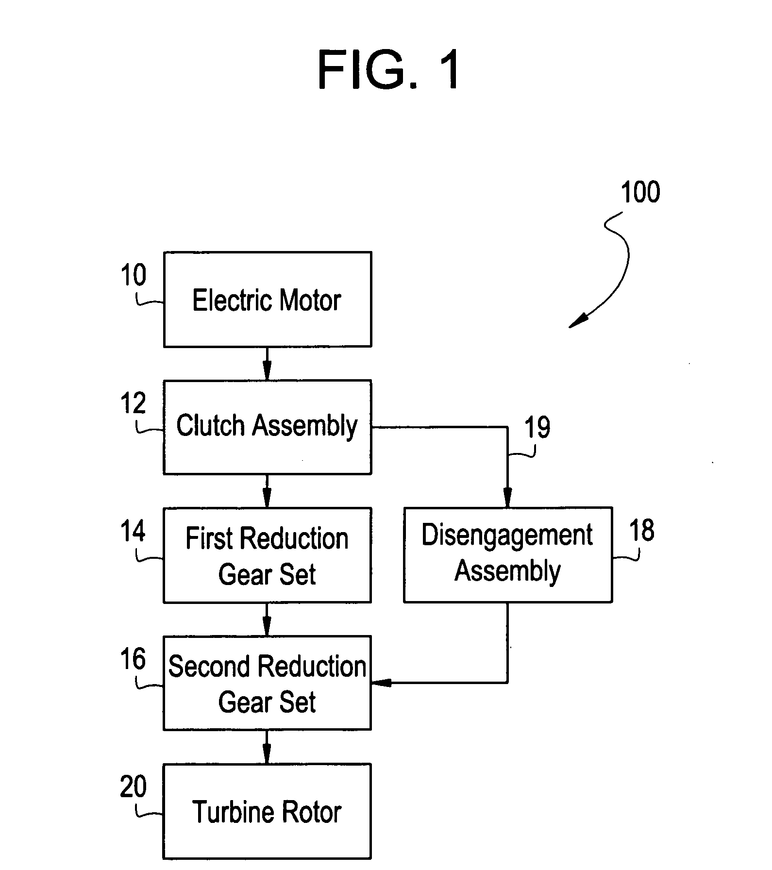
[0015]FIG. 1 illustrates a block diagram of a turning gear assembly according to an exemplary embodiment. The turning gear assembly 100 includes an electric motor 10, a clutch assembly 12, a first gear reduction set 14, a second gear reduction set 16, a disengagement assembly 18, and a turbine rotor 20. It should be noted that although the disclosure describes a turning gear assembly having an electric motor, any other suitable means of providing a rotational output is also envisioned.

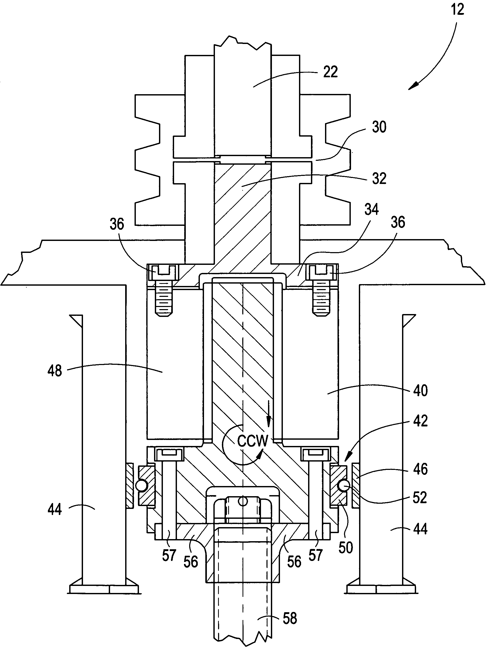
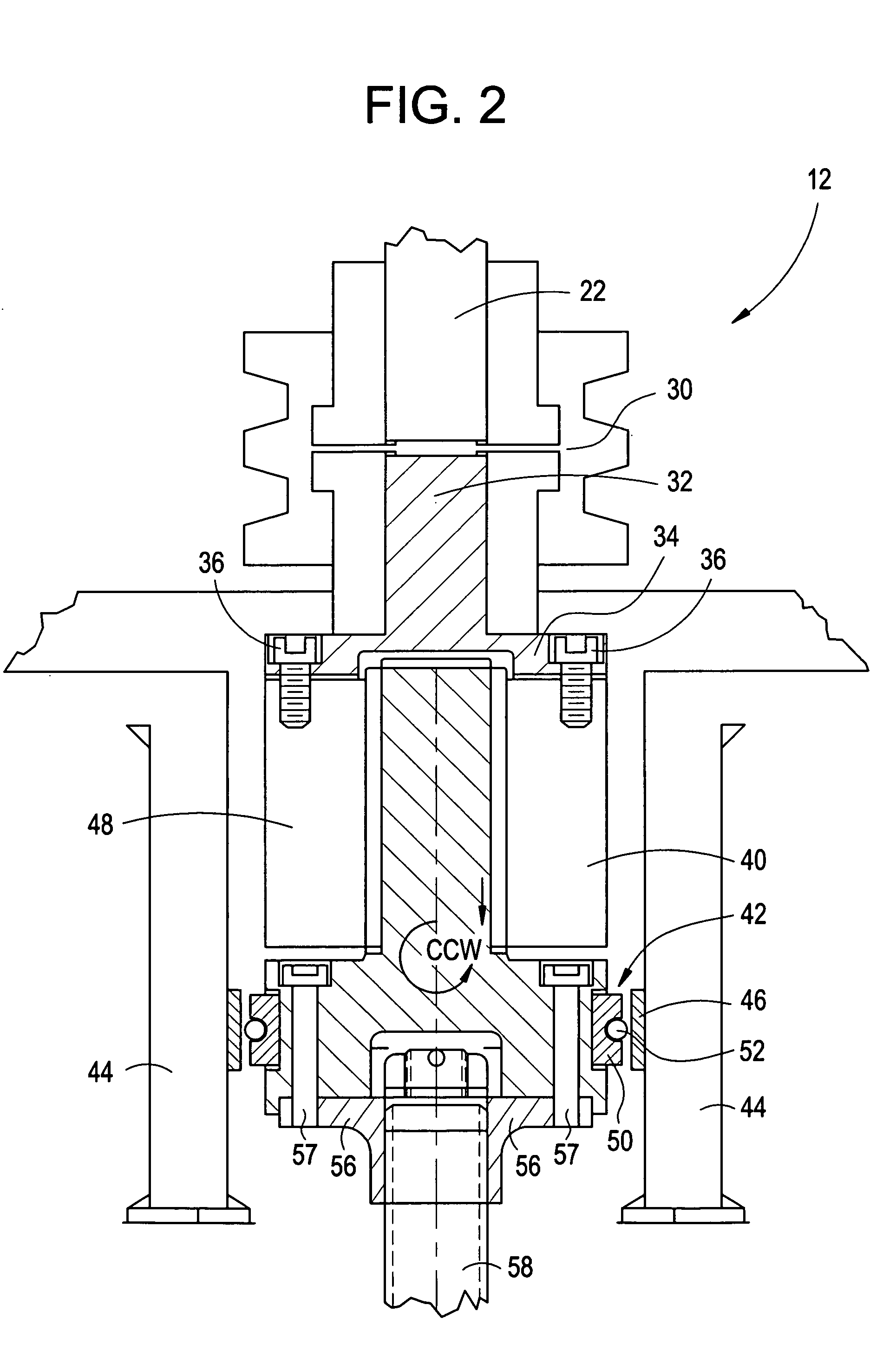
[0016] The electric motor 10 of an exemplary embodiment is a synchronous alternating current (AC) motor, however, any suitable electric motor is envisioned including a direct current (DC) motor. The electric motor 10 converts electrical energy into mechanical energy in the form of torque exerted on a motor shaft 22 (see FIG. 2), causing the motor shaft 22 to rotate at a first speed. The motor shaft 22 translates an output of the electric motor 10 to the first reduction gear set 14 via the clutch assem...


PUM


Abstract

A clutch assembly for a turning gear includes an overspeed clutch, an output shaft, and a centrifugal clutch. The overspeed clutch is disposed at the input shaft. The output shaft is in mechanical communication with the input shaft via the overspeed clutch. The centrifugal clutch is disposed at a portion of the output shaft.

Description

BACKGROUND OF THE INVENTION [0001] The present invention relates to a turning gear for a turbine and, more particularly, to a clutch assembly for use in a turning gear for a steam turbine. [0002] Steam turbines are commonly used to drive electrical generators in power plants. A typical steam turbine is a massive yet intricate piece of machinery that must be started up and shut down in a controlled manner in order to protect each of many steam turbine components from damage due to thermal stresses. Damage due to thermal stresses often results from uneven cooling of components during shutdown or uneven heating of components during startup. [0003] An example of a steam turbine component that is particularly sensitive to thermal stresses during shutdown or startup, is a turbine rotor. For example, the turbine rotor of a steam turbine that is being started up with gland sealing steam cut in will bow or distort if left stationary even for a few minutes. Similarly, a stationary turbine rot...

Claims


Application Information

Patent Timeline
IPC IPC(8): B63H15/00
CPCF01D25/36F16D41/00F05D2260/4031
Inventor HANSEN, WILLIAM SIGURD
Owner GENERAL ELECTRIC CO
Why Eureka
Try Eureka