Fuel cell generation system

Inactive Publication Date: 2006-08-24
PANASONIC CORP
View PDF3 Cites 8 Cited by
  • Summary
  • Abstract
  • Description
  • Claims
  • Application Information

AI Technical Summary

Benefits of technology

[0018] The present invention is directed to solving the above described problems associated with the prior arts, and an object of the present invention is to provide a power generation system with high energy utilization efficiency, which is capable of inhibiting unnecessary

Problems solved by technology

In such a configuration, since the time periods and the stop conditions are pre-set, unnec

Method used


Image

  • Fuel cell generation system
  • Fuel cell generation system
  • Fuel cell generation system

Examples


Example

[0042] A first embodiment of the present invention illustrates that a power threshold condition associated with a power generation operation of a fuel cell is varied according to a use status of a fuel cell system.

[0043] First of all, a construction of the fuel cell system according to the first embodiment of the present invention will be described with reference to the drawings.

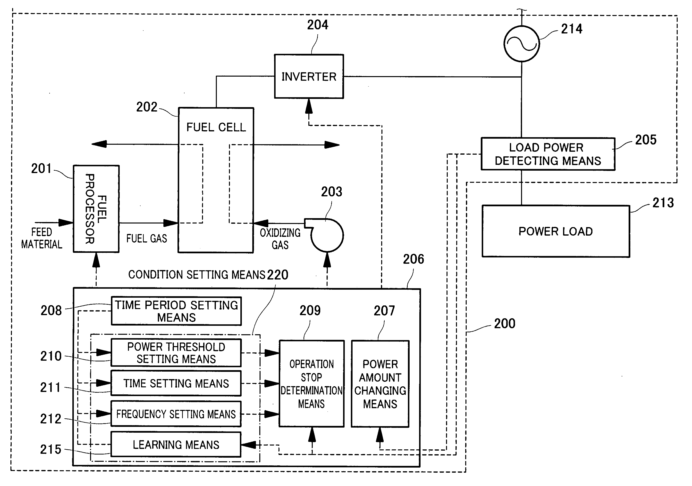
[0044]FIG. 5 is a block diagram schematically showing the construction of the fuel cell system according to the first embodiment of the present invention.

[0045] As shown in FIG. 5, a fuel cell system 200 according to this embodiment comprises a fuel processor 201 configured to convert a feed material such as a natural gas into hydrogen through a steam reforming reaction to generate a fuel gas containing plenty of hydrogen and to supply the fuel gas to a fuel cell 202 described later, an air blower 203 configured to supply air as an oxidizing gas to the fuel cell 202, the fuel cell 202 configured to genera...

Example

[0066] A second embodiment of the present invention illustrates that a frequency condition is added to the condition associated with the start-up or the stop of the fuel cell system, regarding the operation conditions of the fuel cell in the fuel cell system.

[0067] Since the fuel cell system of the second embodiment of the present invention is identical to that of the fuel cell system 200 of the first embodiment, it will not be further described. In addition, an example of an operation pattern of the fuel cell system during a day of the second embodiment of the present invention is similar to the example of the operations pattern of the first embodiment, and therefore, difference between the first embodiment and the second embodiment will be described herein.

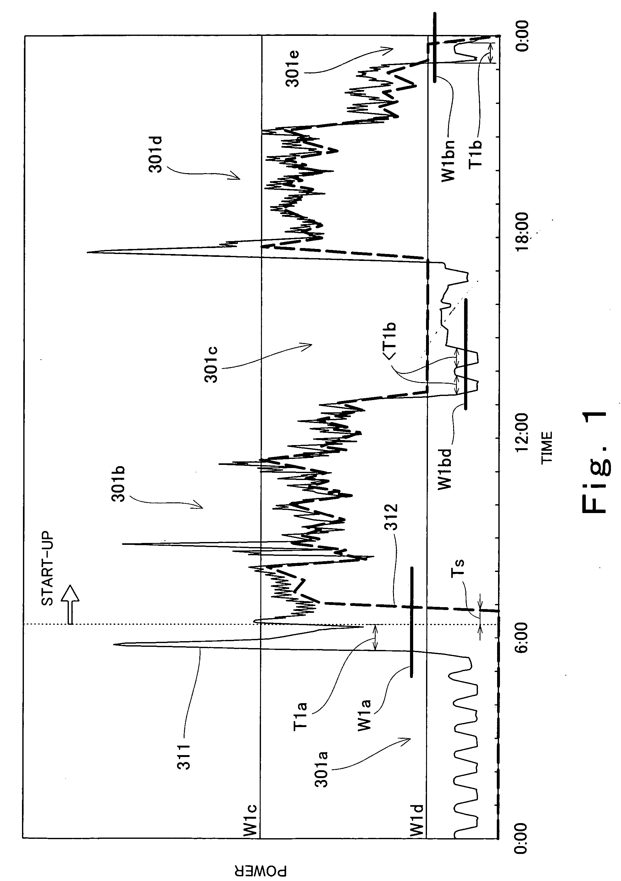
[0068]FIG. 2 is a view schematically showing the example of the operation pattern of the fuel cell system according to the second embodiment of the present invention. In FIG. 2, an ordinate axis indicates a power axis and an a...

Example

[0079] A third embodiment of the present invention illustrates that a time condition associated with a power generation operation of a fuel cell is varied according to a use status of a fuel cell system.

[0080] Since the fuel cell system according to the third embodiment of the present invention is identical in construction to the fuel cell system 200 described in the first embodiment, it will not be further described. In addition, since an operation pattern example during a day of the fuel cell system of the third embodiment is similar to the operation pattern example described in the first embodiment, difference between the first embodiment and the third embodiment will be described in detail.

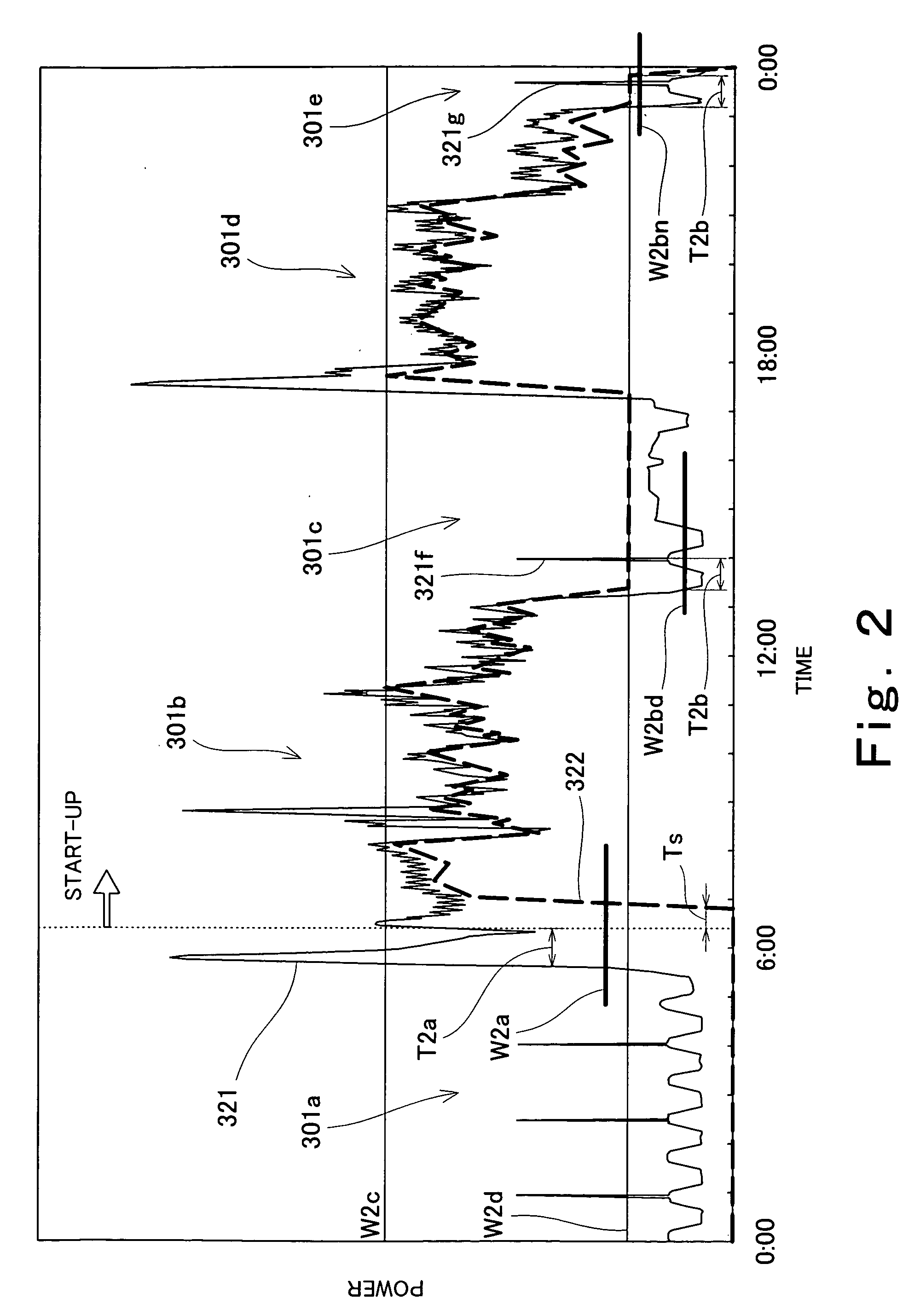
[0081]FIG. 3 is a view schematically showing the operation pattern during a day of the fuel cell system according to the third embodiment of the present invention. In FIG. 3, an ordinate axis indicates a power axis and an abscissa axis indicates a time axis.

[0082] In FIG. 3, a curve 331 ind...


PUM


Abstract

A power generation system (200) of the present invention comprises a power generation portion (202) configured to generate power, a load power detecting means (205) configured to detect a load power supplied from a power source including the power generation portion to a load, an operation stop determination means (209) configured to stop a power generation operation of the power generation portion based on the load power detected by the load power detecting means and a stop condition; and a stop condition setting means (220) configured to set the stop condition, wherein the stop condition setting means sets different stop conditions in a plurality of time periods, and wherein the operation stop determination means stops the power generation operation of the power generation portion based on each of the different stop conditions set by the stop condition setting means and the load power detected by the load power detecting means.

Description

TECHNICAL FIELD [0001] The present invention relates to a power generation system and an operation method thereof and, particularly to a fuel cell system configured to generate power using a fuel cell and an operation method thereof. BACKGROUND ART [0002] Traditionally, a fuel cell system capable of highly efficient and small-scale power generation easily constructs a system for utilizing a heat energy generated during power generation and achieves high energy utilization efficiency. Therefore, the fuel cell system is suitably used as a distributed power generation system. [0003] The fuel cell system comprises a fuel cell which is a base portion of a power generation portion. As the fuel cell, for example, a polymer electrolyte fuel cell or a phosphoric acid fuel cell is typically employed. In these fuel cell systems, a hydrogen-rich gas containing plenty of hydrogen (hereinafter referred to as a fuel gas) and air (hereinafter referred to as an oxidizing gas) are used to generate po...

Claims


Application Information

Patent Timeline
IPC IPC(8): H01M8/04H01M8/06F02K9/00H02J3/28
CPCH01M8/04223H01M8/04298H01M8/04537H01M8/04955H01M8/0612H01M16/006H02J3/28H02J2001/004Y02E60/50H01M8/04228H01M8/04303H02J2300/30Y02E60/10Y02P90/40
Inventor NAKAMURA, AKINARIOZEKI, MASATAKATANAKA, YOSHIKAZUNISHIKAWA, TAKASHI
Owner PANASONIC CORP
Why Eureka
Try Eureka