Lens unit and projection screen made of the same

a technology of lens unit and projection screen, which is applied in the direction of optics, projectors, instruments, etc., can solve the problems of difficult to clearly see the content of the projection image, the contrast of the projection image on the projection screen becomes worse, and the adverse effect of affecting the projection, so as to improve the energy utilization efficiency of incident light. , the effect of increasing the optical gain

Active Publication Date: 2010-07-01
IND TECH RES INST
View PDF12 Cites 7 Cited by
  • Summary
  • Abstract
  • Description
  • Claims
  • Application Information

AI Technical Summary

Benefits of technology

[0023]According to another embodiment of the present invention, the scattering layer of the lens unit can be used to adjust the viewing angle of the projection screen and improve the energy utilization efficiency of incident light. Therefore, the projection screen made of the lens unit according to an embodiment of the present invention has a horizontal viewing angle close to that of a Lambertian surface and an increased optical gain.
[0024]Therefore, the lens unit and the projection screen made of the lens unit according to an embodiment of the present invention overcome the conventional drawbacks including (1) high energy utilization efficiency of incident light but small viewing angle occurring to a projection screen made of a lens unit with a mirror surface; and (2) large viewing angle but low energy utilization efficiency of incident light occurring to a projection screen made of a lens unit with a Lambertian surface.
[0025]Accordingly, a projection screen having large viewing angle, high optical gain and high image contrast is achieved by the lens unit according to an embodiment of the present invention.

Problems solved by technology

Although the projectors and projection screens are improved with advanced technology, some drawbacks exist in the front projection technology used in a projector or projection screen.
For example, when using the projector or projection screen, the ambient light from the ambient environment of the projector will adversely affect the projection.
When the ambient light becomes stronger, the contrast of projection images on the projection screen becomes worse.
As a result, it becomes difficult to clearly see the content of the projection images.
Nevertheless in usual circumstances, such as in teaching or meeting presentations, complete elimination of the ambient light will cause inconvenience to the audiences who may need to make some notes.
However, miniaturized projectors lack high luminance light sources.
Therefore, poor contrast of projection images on the projection screen caused by the ambient light becomes much more serious.
However, the method still has some drawbacks to be solved.

Method used


Image

  • Lens unit and projection screen made of the same
  • Lens unit and projection screen made of the same
  • Lens unit and projection screen made of the same

Examples


Embodiment Construction

[0044]The following illustrative embodiments are provided to illustrate the disclosure of the present invention, these and other advantages and effects can be apparent to those skilled in the art after reading the disclosure of this specification.

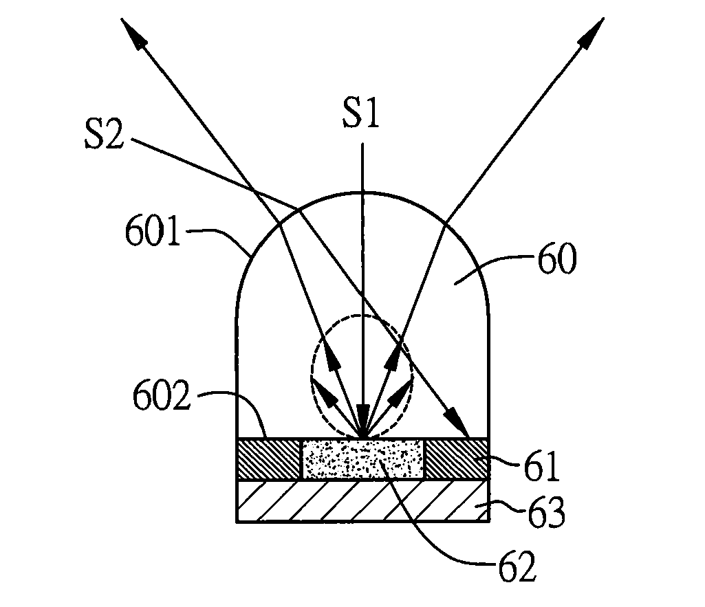
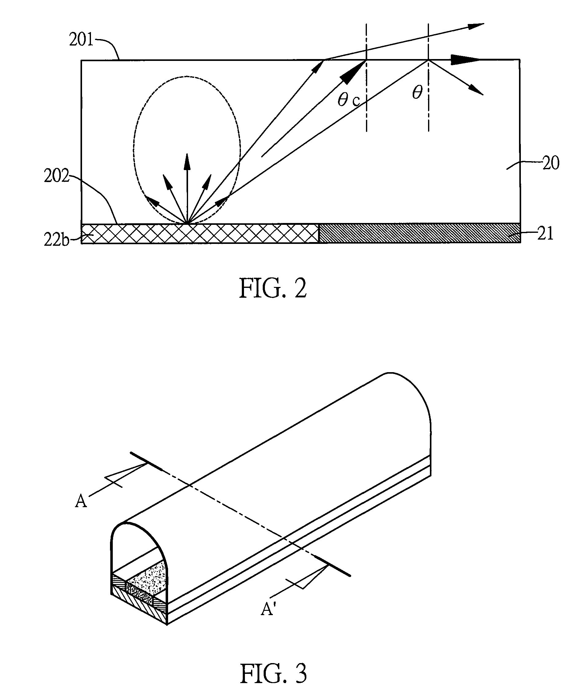
[0045]FIG. 3 shows a lens unit according to an embodiment of the present invention. FIG. 4A is a cross-sectional view showing the lens unit taken along sectional line AA′ of FIG. 3. FIG. 4B is a schematic view showing scattering of incident light by the lens unit of FIG. 4A. FIG. 4C is a schematic view showing sizes of the component parts of the lens unit of FIG. 4A.

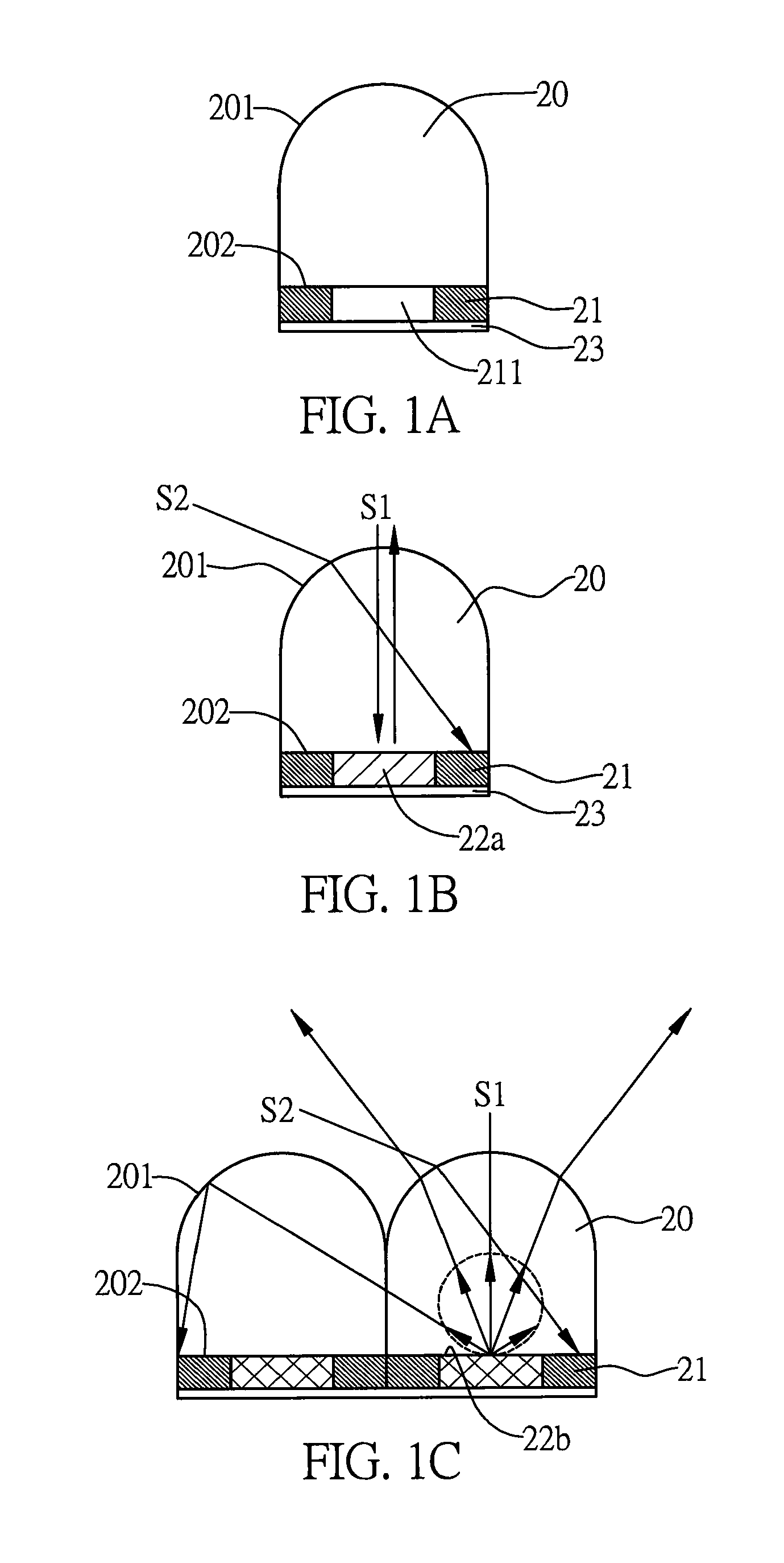
[0046]As shown in FIG. 4A, a lens unit includes a micro lens 60, a light absorbing layer 61, a scattering layer 62 and a reflective layer 63. The micro lens 60 has a light incident surface 601 and a light emergent surface 602 opposing to the light incident surface 601, wherein the micro lens is made of a transparent material without absorbing light. The light absorbing layer 61 ...


PUM


Abstract

A lens unit and a projection screen made of the same are disclosed. The lens unit includes a micro lens having a light incident surface and a light emergent surface opposing to the light incident surface; a light absorbing layer formed on the light emergent surface of the micro lens and having a cavity formed therein; a scattering layer formed in the cavity of the light absorbing layer and including a transparent resin blended with scattering particles; and a reflective layer formed on the light absorbing layer and the scattering layer. The projection screen includes a plurality of the lens units, thereby achieving high contrast and high energy utilization efficiency of incident light with a large viewing angle.

Description

BACKGROUND OF THE INVENTION[0001]1. Field of the Invention[0002]The present invention generally relates to lens units and projection screens made of the same, and more particularly to a lens unit with a scattering layer comprising a transparent resin blended with scattering particles and a projection screen including the lens unit.[0003]2. Description of Related Art[0004]Currently, projectors and projection screens have been widely used in teaching, meeting presentation, advertising, entertainment and so on. Although the projectors and projection screens are improved with advanced technology, some drawbacks exist in the front projection technology used in a projector or projection screen. For example, when using the projector or projection screen, the ambient light from the ambient environment of the projector will adversely affect the projection. When the ambient light becomes stronger, the contrast of projection images on the projection screen becomes worse. As a result, it become...

Claims


Application Information

Patent Timeline
Patent Type & Authority Applications(United States)
IPC IPC(8): G03B21/60G02B17/00
CPCG03B21/60
Inventor LIN, DING-ZHENGWU, YAW-TINGCHANG, YOU-CHIAWEN, CHUN-HSIANGYEH, JYI-TYAN
Owner IND TECH RES INST
Why Eureka
Try Eureka