Switch circuit with independent DC power supply

Inactive Publication Date: 2012-05-03
HUO WEIMIN +1
View PDF1 Cites 3 Cited by
  • Summary
  • Abstract
  • Description
  • Claims
  • Application Information

AI Technical Summary

Benefits of technology

[0041]The present invention effectively solves the problem of a waste of power consumption due to redundant power supply generated by the power supply unit when the switch unit is turned off in the conventional switch circuit sharing the DC power supply source with the control unit. Then, the present inve

Problems solved by technology

However, power consumption of the control unit is low, generally from tens of microamperes to milliamps, while the switch unit has higher power consumption than the control unit.
When the power supply unit adopts a capacitor vol

Method used


Image

  • Switch circuit with independent DC power supply
  • Switch circuit with independent DC power supply
  • Switch circuit with independent DC power supply

Examples


Embodiment Construction

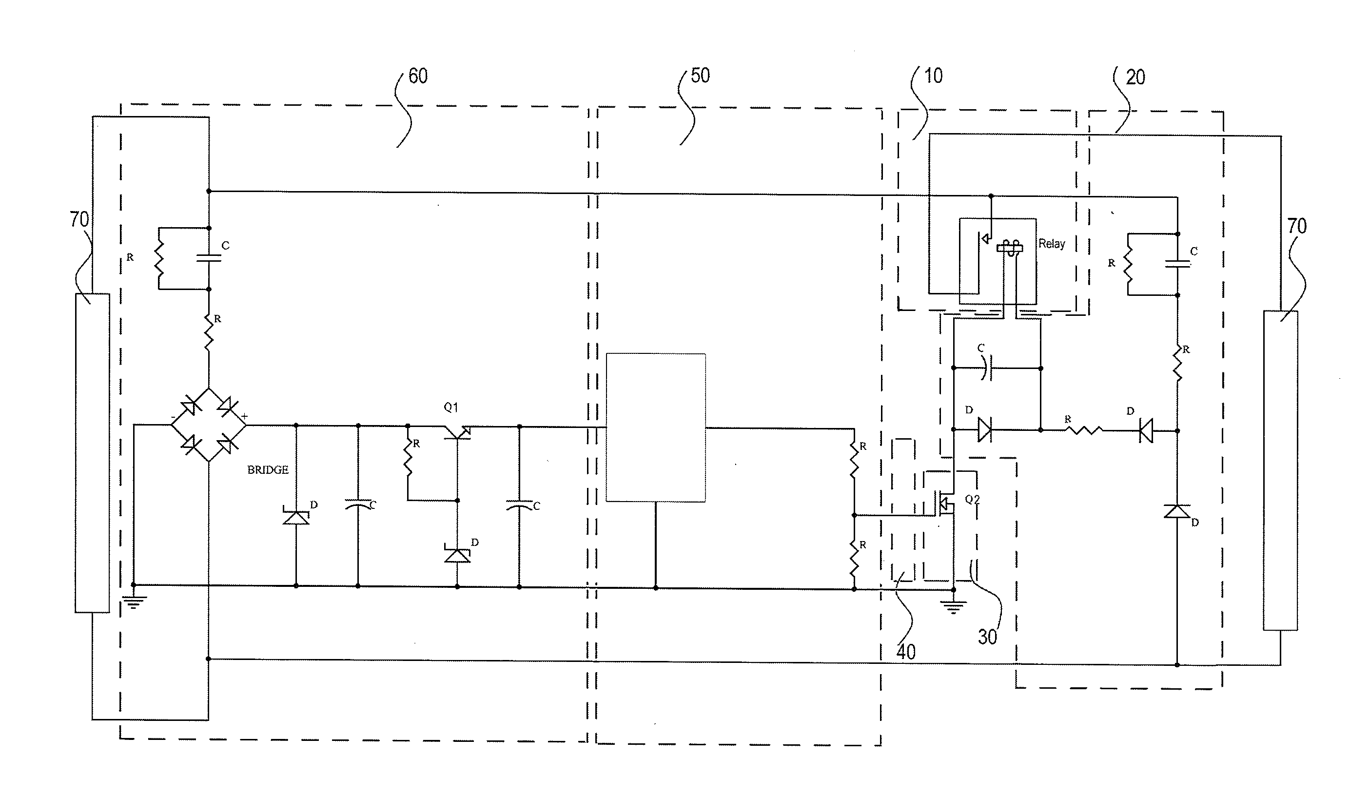
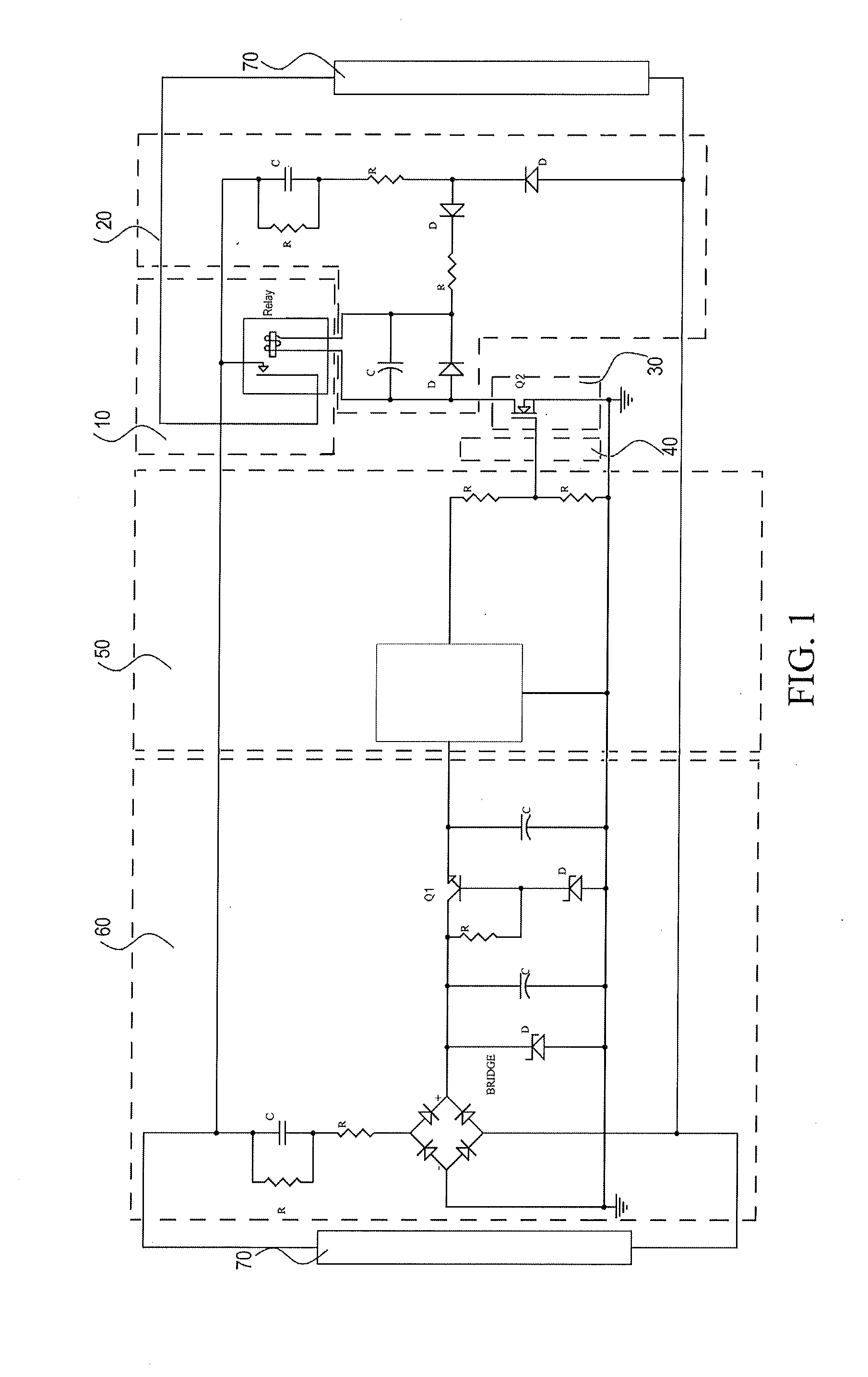
[0045]A switch circuit with independent DC power supply of the present invention adopts an independent power supply unit different from a power supply unit of a control unit, and the power supply unit of the switch unit is turned on as the switch unit is turned on and is turned off as the switch unit is turned off.

[0046]As shown in FIG. 1, in a switch circuit with independent DC power supply, a switch device used by a switch unit 10 is a DC-driven relay. In a power supply unit 20 of the switch unit, a rectification circuit is a half-bridge diode rectification circuit, and a voltage dropping circuit is a capacitor voltage dropping circuit. A switch device of an on / off unit 30 of the power supply unit of the switch unit is a voltage-driven field effect transistor (FET) Q2. A power supply unit 60 of a control unit is a bridge diode rectification circuit, and the power supply unit 60 and the power supply unit 20 of the switch unit adopting the half-bridge diode rectification circuit may...


PUM


Abstract

A switch circuit with independent direct current (DC) power supply is provided. The switch circuit includes a switch unit, a power supply unit of the switch unit, an on/off unit of the power supply unit, and/or an on/off unit of the switch unit, and an on/off control signal transmission unit. Through the switch circuit with independent DC power supply, the problem of a waste of power consumption due to redundant power supply generated by a power supply unit when a switch unit is turned off in a conventional switch circuit sharing a DC power supply source with a control unit is effectively solved. In the provided switch circuit, the control unit and the switch unit respectively have independent power supply units, the power supply unit of the switch unit is turned on only when the switch unit needs to be turned on, and the power supply unit is turned off when the switch unit is turned off.

Description

BACKGROUND OF THE INVENTION[0001]1. Field of Invention[0002]The present invention relates to an electronic switch circuit, and more particularly, to a switch circuit with independent direct current (DC) power supply.[0003]2. Related Art[0004]Generally, a switch unit and a control unit of an electronic switch circuit share a power supply unit. However, power consumption of the control unit is low, generally from tens of microamperes to milliamps, while the switch unit has higher power consumption than the control unit. For example, a driving current of a relay or controlled silicon is about tens of milliamps, and the power consumption of the switch unit may be over ten times higher than the control unit. In this way, in order to meet the requirements of the switch unit for power supply when the switch unit is turned on, the power supply unit needs to maintain a redundant power supply capability much greater than that required by the control unit. When the power supply unit adopts a c...

Claims


Application Information

Patent Timeline
IPC IPC(8): H01H47/22
CPCH01H47/325H03K17/691H03K17/723H03K2217/0081
Inventor HUO, WEIMINSUI, HAIYAN
Owner HUO WEIMIN
Why Eureka
Try Eureka