Pelvic traction harness

a technology of traction harnesses and torsos, applied in the field of traction harnesses, can solve the problems of increasing disadvantages, reducing the frequency of movement, and reducing so as to reduce the incidence of movement, reduce the discomfort of patients, and produce a localized traction force around the torso

Inactive Publication Date: 2006-08-24
ENCORE MEDICAL ASSET CORP
View PDF16 Cites 41 Cited by
  • Summary
  • Abstract
  • Description
  • Claims
  • Application Information

AI Technical Summary

Benefits of technology

[0007] Accordingly, it is an advantage of the invention claimed herein to provide an apparatus and method for producing a more securely bearing engagement between the apparatus and the iliac crests of the os coxae bones of the pelvic girdle of a patient, thereby reducing the incidence of movement of the harness relative to the torso of the patient in the direction of a traction force applied thereto. It is also an advantage of the invention claimed herein to provide such an apparatus and method for producing a traction force that is more evenly and completely distributed around the torso of a patient. It is another advantage of the invention claimed herein to provide such an apparatus and method for producing a traction force that is more optimally aligned with the longitudinal axis of the spine of the patient. It is still another advantage of the invention claimed herein to provide such an apparatus and method for producing a traction force that is more optimally balanced along the posterior-anterior axis of the torso of the patient. It is yet another advantage of the invention claimed herein to provide such an apparatus and method that would reduce the discomfort experienced by a patient when a traction force is applied. It is a further advantage of the invention claimed herein to provide such an apparatus and method that would permit the apparatus to be secured around the torso of a patient while the patient is in a supine position. It is a still further advantage of the invention claimed herein to provide such an apparatus and method for producing a cinching force around the torso of a patient. It is also an advantage of the invention claimed herein to provide such an apparatus and method for producing a localized cinching force around the torso of a patient. It is another advantage of the invention claimed herein to provide such an apparatus and method for producing a pair of distinct cinching force distributions whereby the two cinching force distributions are generally opposed to each other and directed along non-parallel planes.
[0008] Additional advantages of this invention will become apparent from an examination of the drawings and the ensuing description. EXPLANATION OF TECHNICAL TERMS
[0009] As used herein, the term cinching effect refers to the constricting effect achieved by producing a pair of distinct, non-parallel pulling forces around the torso of a patient, whereby one of the distinct, non-parallel pulling forces is generally directed toward the anterior of the patient and the other distinct, non-parallel parallel pulling force is generally directed toward the posterior of the patient. In a preferred embodiment of the invention claimed herein, the two distinct, non-parallel pulling force distributions applied around the torso of the patient produce a V-shaped force vector configuration when viewed as a cross-section cut along the posterior-anterior plane of the patient. The cinching effect achieved by the invention claimed herein is produced, in part, by providing a pair of separate belts adapted to be secured around the torso of a patient such that each may move relative to the other. Additional factors that contribute to the cinching effect achieved by the invention claimed herein include, but are not limited to, the following: a pulling force is applied to only the anterior of the cinching strap belt; a pulling force is applied to only the posterior of the circumferential belt; the cinching strap belt is narrow; and the cinching strap belt is loosely secured to the circumferential belt such that the cinching strap belt may move relative to the circumferential belt in the general direction of the pulling force applied to the cinching strap belt. SUMMARY OF THE INVENTION
[0010] The invention comprises an apparatus and method for a pelvic traction harness comprising a circumferential belt, a cinching strap belt, and a pulling strap. More particularly, the apparatus of the invention includes a circumferential belt having a first end, a second end opposite the first end, a fastening means for adjustably securing the circumferential belt around the torso of the patient, and a posterior area intermediate the first end and the second end. The circumferential belt is adapted to be secured around the torso of a patient such that the posterior area of the circumferential belt is adjacent to the lower spine of the patient. In addition, a cinching strap belt having a male end, a female end, and an anterior region intermediate the male and female end. The cinching strap belt is adapted to be secured around the circumferential belt such that the anterior region of the cinching strap belt is opposite the posterior area of the circumferential belt. The invention further comprises a pulling strap having an anterior end and a posterior end. The anterior end of the pulling strap is adapted to be attached to the anterior region of the cinching strap belt, and the posterior end of the pulling strap is adapted to be attached to the posterior area of the circumferential belt. Further, the pulling strap is adapted to extend between the legs of the patient and attach to a source for applying a pulling force.
[0011] According to the method of the invention, a traction force is applied to the spine of a patient through the application of a pulling force to the pelvic region of the patient. More particularly, the method of the invention includes providing a circumferential belt having a first end, a second end opposite the first end, a posterior area intermediate the first end and the second end, a means for securing the first end to the second end, and a belt loop. The first end of the circumferential belt is secured to the second end such that the circumferential belt extends around the torso of a patient and the posterior area is adjacent to the lower spine of the patient.
[0012] In addition, the method includes providing a cinching strap belt having a male end, a female end opposite the male end, an anterior region intermediate the male end and the female end, a means for securing the male end to the female end, and a means for receiving a pulling strap in the anterior region of the cinching strap belt. The cinching strap belt is passed through the belt loop, and the male end of the cinching strap belt is secured to the female end such that the cinching strap belt extends around the circumferential belt and the anterior region of the cinching strap belt is opposite the posterior area of the circumferential belt.

Problems solved by technology

However, these conventional devices suffer from one or more disadvantages.
Conventional belts also produce an uncomfortable squeezing or pinching force around the torso of the patient.
These disadvantages become more pronounced in a patient having excess body mass in the area of the iliac crests.
Thereafter, when the patient assumes the prone position, the conventional belt is frequently not sufficiently tight to securely bear against the iliac crests of the patient when a traction force is applied.
Again, these disadvantages are more pronounced when a patient has excess body mass in the area of the iliac crests.
As a result of the foregoing disadvantages, conventional devices are susceptible to movement relative to the torso of a patient in the direction of the pulling force and even losing a bearing engagement with the iliac crests of the patient when a traction force is applied.
In addition, conventional devices do not produce a traction force that is optimally distributed around the torso of the patient.
Further, conventional devices do not produce a traction force that is optimally aligned with the spine of the patient or optimally balanced along the posterior-anterior axis of the torso of the patient.

Method used


Image

  • Pelvic traction harness
  • Pelvic traction harness
  • Pelvic traction harness

Examples


Embodiment Construction

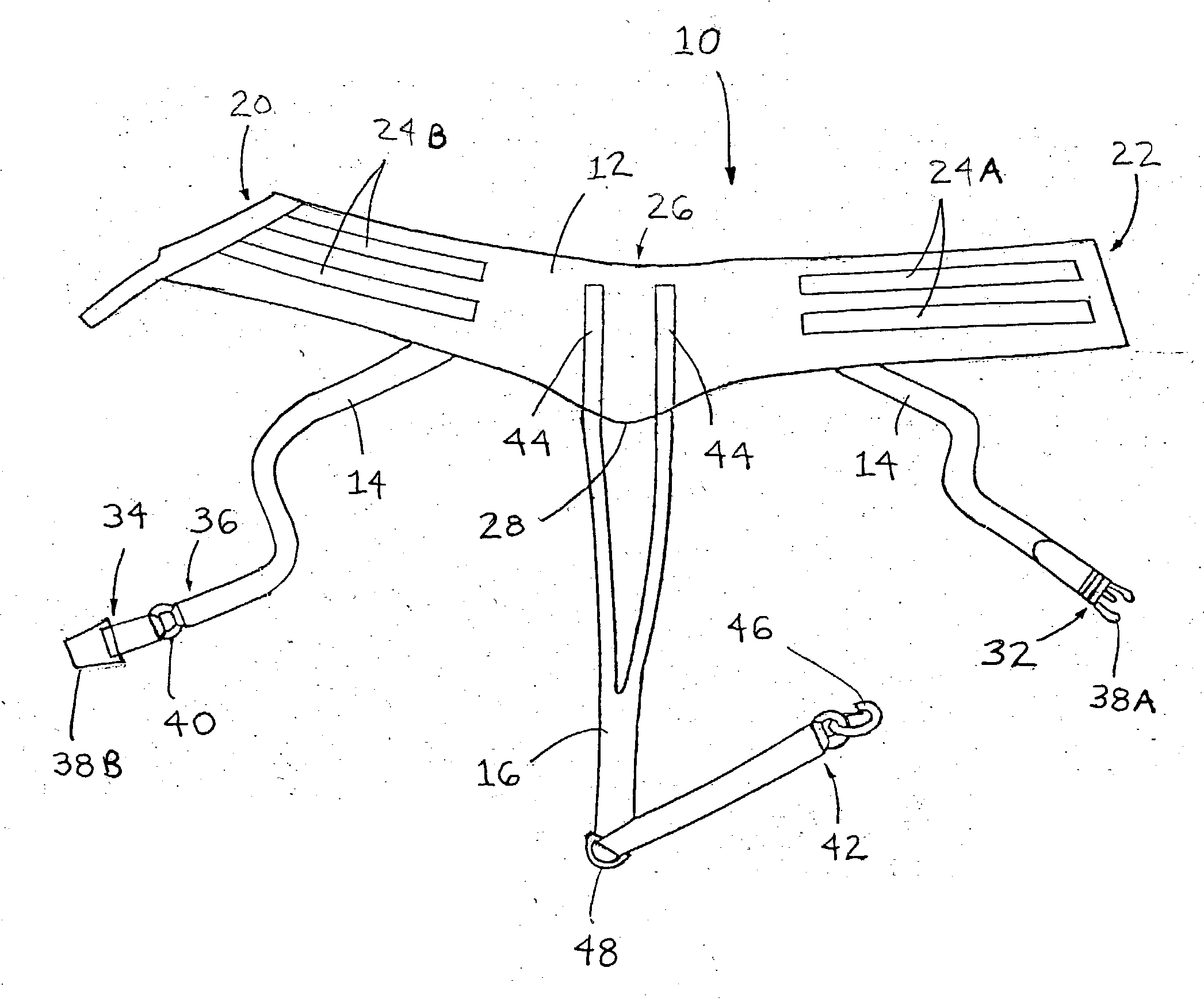
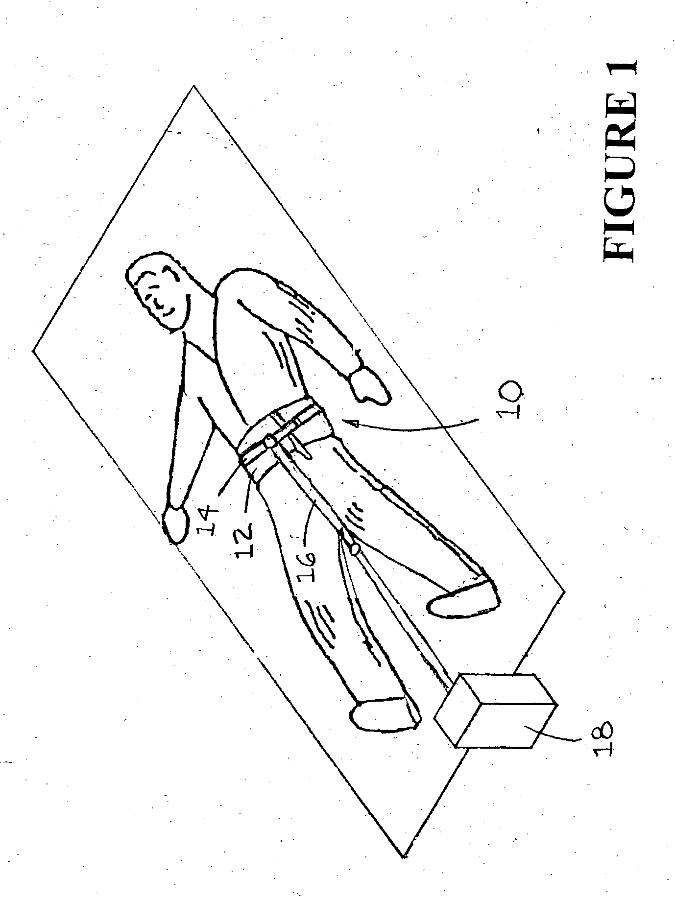
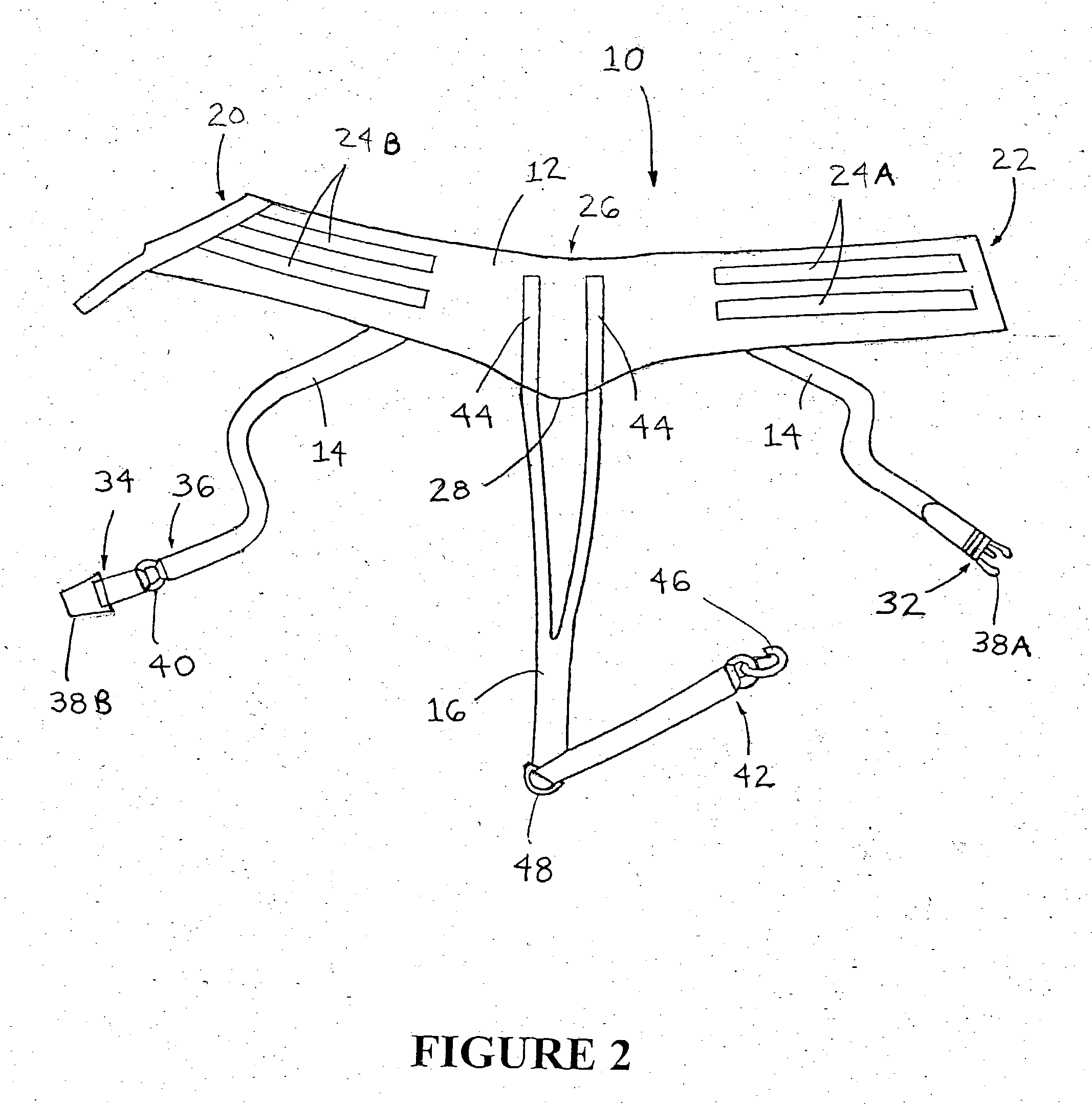
[0024] Referring now to the drawings, the apparatus and method of the invention are illustrated by FIGS. 1 through 7. FIG. 1 illustrates a preferred embodiment of the pelvic traction harness of the invention which is designated generally by reference numeral 10. More particularly, FIG. 1 illustrates a preferred embodiment of the pelvic traction harness of the invention being worn by a patient lying in the supine position.

[0025] As shown in FIG. 1, pelvic traction harness 10 generally includes circumferential belt 12 (See also FIGS. 2 and 3), cinching strap belt 14 (See also FIGS. 2 and 4) and pulling strap 16 (See also FIGS. 2 and 5). Circumferential belt 12 and cinching strap belt 14 are adapted to be secured around the torso of a patient. Pulling strap 16 is adapted to be attached to the circumferential belt on one end and to the cinching strap belt on the other end such that the pulling strap extends between the legs of a patient. The pulling strap is adapted to be attached to a...


PUM


Abstract

A pelvic traction harness including a circumferential belt that is adapted to be secured around the torso of a patient and has a first end, a second end and a posterior area intermediate the first end and the second end. The harness also includes a separate cinching strap belt that is adapted to be secured around the circumferential belt and has a male end, a female end and an anterior region intermediate the male end and the female end. The harness also includes a pulling strap having an anterior end and a posterior end, said anterior end being adapted to be attached to anterior region of the cinching strap belt, said posterior end being adapted to be attached to the posterior area of the circumferential belt. The pulling strap is also adapted to extend between the legs of the patient and attach to a source for applying a pulling force. The invention also includes a method for applying a traction force to the spine of a patient through the pelvic region of the patient.

Description

FIELD OF THE INVENTION [0001] This invention relates generally to pelvic traction harnesses used to apply a traction force to the spine of a patient through the pelvic area. More particularly, the invention relates to an apparatus and method for applying a balanced, evenly-distributed, and properly aligned traction force to the spine of a patient through the application of pulling force to the pelvic area of the patient. BACKGROUND OF THE INVENTION [0002] It is known to apply a traction force to the spine of a patient by securing around the pelvic region of a patient a belt or harness having one or more pulling straps. See, e.g., U.S. Pat. Nos. 4,995,378; 4,073,290; and 3,561,434. It is further known to attach the pulling strap or straps to a pulling device. Typically, traction force is applied by a pulling device located near the feet of the patient while the patient is in a prone position. Consequently, when the pulling device is attached to the pulling strap, a pulling force is a...

Claims


Application Information

Patent Timeline
Patent Type & Authority Applications(United States)
IPC IPC(8): A61F5/00
CPCA61F5/3769A61H1/0218A61H1/0222A61H2201/163
Inventor KENNEDY, JAY
Owner ENCORE MEDICAL ASSET CORP
Why Eureka
Try Eureka