Autonomous surface cleaning robot for wet cleaning

Active Publication Date: 2006-08-24
IROBOT CORP
View PDF101 Cites 176 Cited by
  • Summary
  • Abstract
  • Description
  • Claims
  • Application Information

AI Technical Summary

Benefits of technology

[0042] In still other embodiments, the method includes smearing the cleaning fluid across the cleaning width using a smearing element attached to the chassis aft of the co-located position of the first nozzle and the second nozzle, said smearing element extending across the cleaning width. Other embodiments may include scrubbing the surface across the cleaning width using a scrubbing element attached to the chassis aft of the co-located position of the first nozzle and the second nozzle, said scrubbing element extending across the cleaning width. Still other embodiments include collecting waste liquid from the surface across the cleaning width using a collecting apparatus attached

Problems solved by technology

While each of the above examples provide affordable autonomous floor clearing robots for collecting loose particulates, there is heretofore no teaching of an affordable autonomous floor cleaning robot for applying a cleaning fluid onto the floor to wet clean floors in the home.
The cleaning fluid interacts with contaminants on the surface and may dissolve or otherwise emulsify contaminants into the cleaning fluid.
One problem with the manual floor cleaning methods of the prior art is that after cleaning an area of the floor surface, the waste liquid must be rinsed from the mop or sponge, and this usually done by dipping the mop or sponge back into the container filled with cleaning fluid.
The rinsing step contaminates the cleaning fluid with waste liquid and the cleaning fluid becomes more contaminated each time the mop or sponge is rinsed.
As a result, the effectiveness of the cleaning fluid deteriorates as more of the floor surface area is cleaned.
While the traditio

Method used


Image

  • Autonomous surface cleaning robot for wet cleaning
  • Autonomous surface cleaning robot for wet cleaning
  • Autonomous surface cleaning robot for wet cleaning

Examples


Embodiment Construction

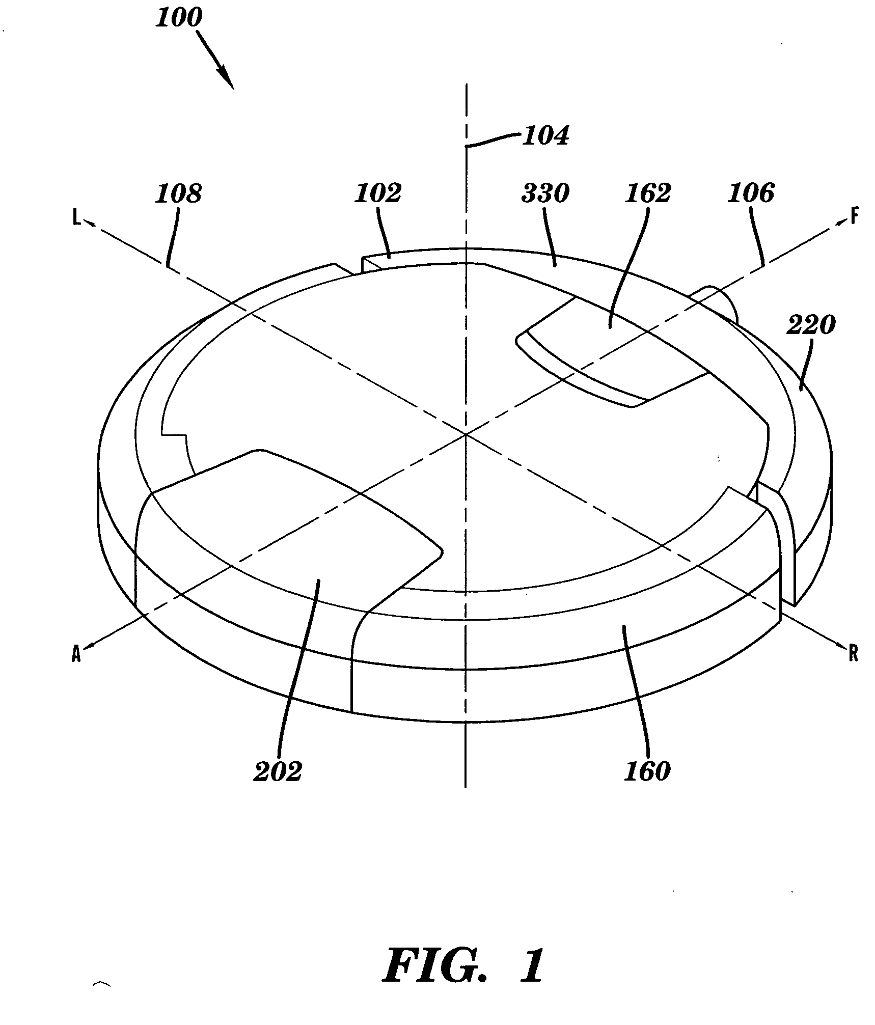
[0065] Referring now to the drawings where like reference numerals identify corresponding or similar elements throughout the several views, FIG. 1 depicts an isometric view showing the external surfaces of an autonomous cleaning robot 100 according to a preferred embodiment of the present invention. The robot 100 is configured with a cylindrical volume having a generally circular cross-section 102 with a top surface and a bottom surface that is substantially parallel and opposed to the top surface. The circular cross-section 102 is defined by three mutually perpendicular axes; a central vertical axis 104, a fore-aft axis 106, and a transverse axis 108. The robot 100 is movably supported with respect to a surface to be cleaned, hereinafter, the cleaning surface. The cleaning surface is substantially horizontal. The robot 100 is generally supported in rolling contact with the cleaning surface by a plurality of wheels or other rolling elements attached to a chassis 200. In a preferred ...


PUM


Abstract

An autonomous floor cleaning robot includes a transport drive and control system arranged for autonomous movement of the robot over a floor for performing cleaning operations. The robot chassis carries a first cleaning zone comprising cleaning elements arranged to suction loose particulates up from the cleaning surface and a second cleaning zone comprising cleaning elements arraigned to apply a cleaning fluid onto the surface and to thereafter collect the cleaning fluid up from the surface after it has been used to clean the surface. The robot chassis carries a supply of cleaning fluid and a waste container for storing waste materials collected up from the cleaning surface.

Description

CROSS-REFERENCE TO RELATED APPLICATIONS [0001] This application claims priority under 35 U.S.C. § 119(e) to U.S. Provisional Application Ser. No. 60 / 654,838, the entire disclosure of which is herein incorporated by reference it its entirety. This application also claims priority under 35 U.S.C. § 120 to U.S. application Ser. No. 11 / 134,212, U.S. application Ser. No. 11 / 134,213, and U.S. application Ser. No. 11 / 133,796, the entire disclosures of which are herein incorporated by reference in their entireties. This application relates to and herein incorporates by reference in their entireties the disclosures of the application entitled “Autonomous Surface Cleaning Robot for Wet and Dry Cleaning,” by Casey et al., filed on even date herewith, and identified by attorney docket no. IRO-017CP1; and the application entitled “Autonomous Surface Cleaning Robot for Dry Cleaning,” by Gilbert et al., filed on even date herewith, and identified by attorney docket no. IRO-017CP2.BACKGROUND OF THE...

Claims


Application Information

Patent Timeline
IPC IPC(8): G06F19/00
CPCA22C17/0013A47L11/292A47L7/0009A47L7/0028A47L7/0038A47L7/0042A47L11/302A47L11/34A47L11/4002A47L11/4011A47L11/4016A47L11/4041A47L11/4044A47L11/4061A47L11/4069A47L11/4072A47L11/4083A47L11/4088A47L2201/00A47L11/28A47L5/14A47L11/4008A47L11/4019A47L2201/04
Inventor KONANDREAS, STEPHANOSZIEGLER, ANDREWMORSE, CHRISTOPHER JOHN
Owner IROBOT CORP
Why Eureka
Try Eureka