
Sensor network management system

a sensor network and management system technology, applied in the field of information processing system, can solve the problems of easy failure of task programs and failure-proofing of sensor network systems, and achieve the effect of improving production factor and physical distribution efficiency, and effective looking up attribute information

Inactive Publication Date: 2006-08-24
HITACHI LTD
View PDF7 Cites 249 Cited by
  • Summary
  • Abstract
  • Description
  • Claims
  • Application Information

AI Technical Summary

Benefits of technology

The invention provides a system for managing a sensor network, which can look up the conditions of a real-world matter and execute task processing by using the sensor nodes as an independent system. The system needs to be able to easily look up the condition of a matter as a measurement object and to manage a plurality of sensor nodes as a single system. The technical effects of the invention include the ability to manage a sensor network as an independent system and the failure-proofing of the system.

Problems solved by technology

Two problems can be mentioned as the problems of the sensor network system.
The first problem is how the task program can easily look up the condition or the attribute value of a matter as a measurement object.
The second problem is how to accomplish failure-proofing of the sensor network system.

Method used


Image

  • Sensor network management system
  • Sensor network management system
  • Sensor network management system

Examples


embodiment 1

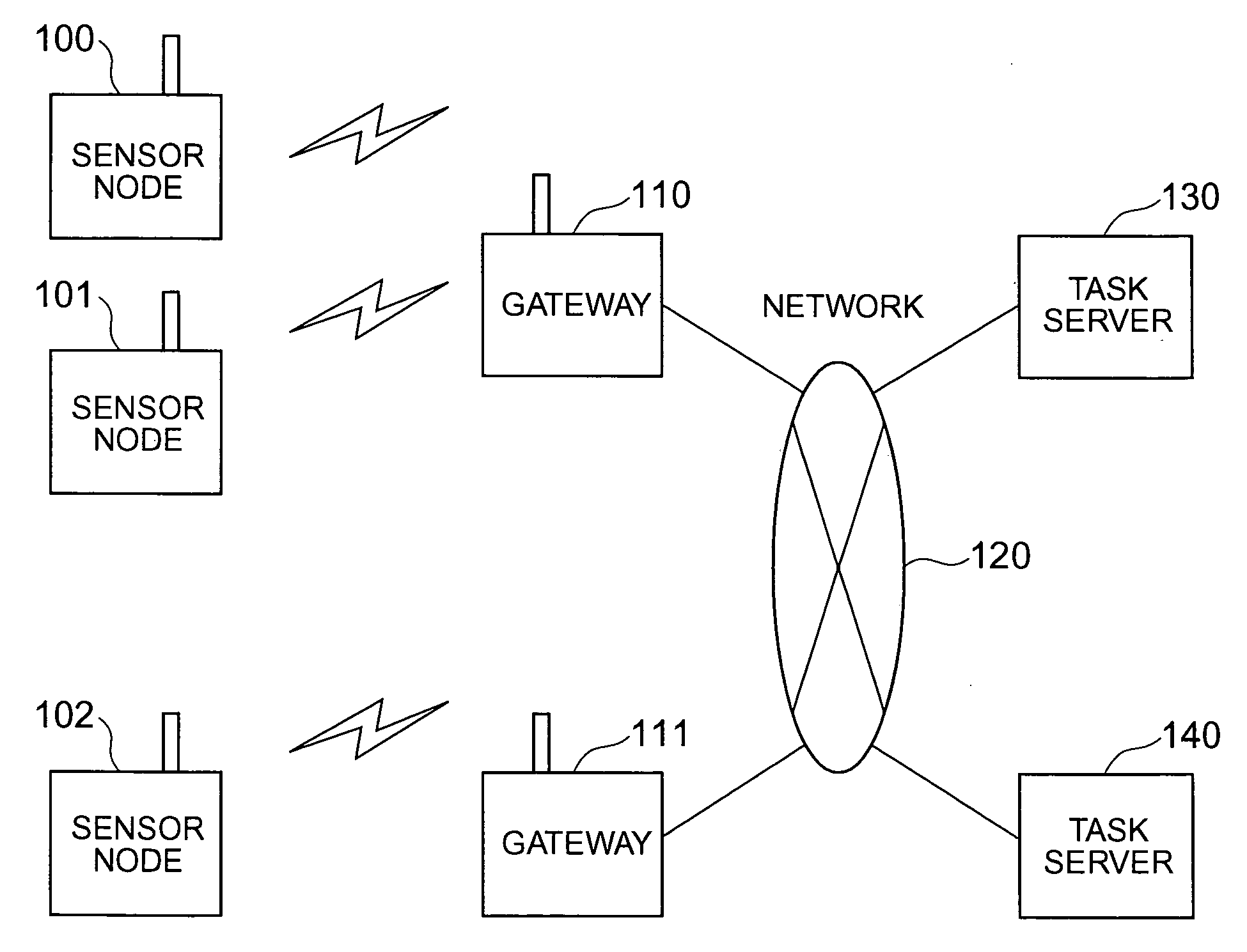
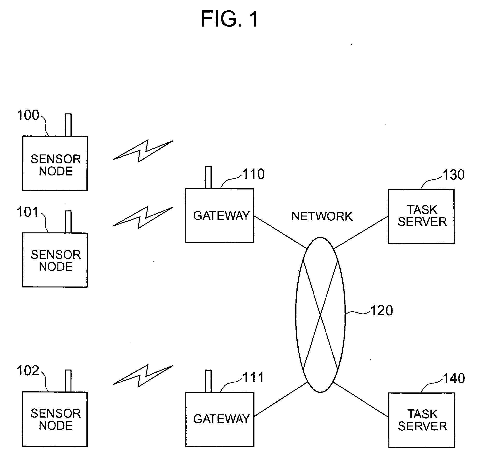
[0059]FIG. 1 shows an overall construction of a sensor network system according to the first embodiment of the invention. The sensor network system includes a plurality of sensor nodes (100, 101, 102), gateways (110, 111), a network (120), a name server (130) and a task server (140).

[0060] Each of the sensor nodes (100, 101, 102) is a terminal computer that has a wireless communication function, measures various kinds of information by using a built-in sensor and exchanges a variety of electronic data containing the measurement information with the gateway (110,111) through the wireless communication function. The gateway (110, 111) is a wireless communication base station computer that has a wireless communication function and an ordinary network communication function typified by the Internet and accomplishes a data conversion processing function between the two different communication protocols described above. The network (120) is a local area network or wide area network typif...

example 2

[0113]FIG. 20 shows an overall construction of a sensor network system according to the second embodiment of the invention. The sensor network system includes a plurality of sensor nodes (2001, 2002), gateways (2011, 2012), a local name server (2030), a global name server (2060), a task server (140), and LANs (2020, 2021, 2022), rooters (2040, 2041, 2042) and a WAN (2050) that together connect the system components described above. In this embodiment, a sensor network operation management system having a failure-proofing function capable of executing tasks in the entire system even when any failure occurs in the sensor nodes and the gateways will be explained. In FIG. 20, dash line encompassing each sensor node represents that the sensor nodes a1 (2001) and a2 (2002) belong to one group constituting virtually one sensor node A (2000). Dash line encompassing each gateway represents that the gateways c1 (2011) and c2 (2012) belong to one group constituting virtually one gateway C (201...


PUM


Abstract

An attribute value of a matter accompanied by a sensor is transmissibly accessible in a sensor node system constituted by wireless terminal computers having the sensor, the wireless communication base stations and server computers. The wireless terminal computer reports at the time of wireless communication an identification number of a wireless communication base station with which it communicates previously. A relay processing service is dynamically constituted so that when a wireless communication base station different from itself is reported, the wireless base station as the communication counter-part can transmissbly look up the wireless terminal computer from a host computer.

Description

INCORPORATION BY REFERENCE [0001] The present application claims priority from Japanese application JP2005-044940 filed on Feb. 22, 2005, the content of which is hereby incorporated by reference into this application. BACKGROUND OF THE INVENTION [0002] This invention relates to an information processing system including information processing terminals each having a wireless communication function, wireless base stations for executing wireless communication with the information processing terminals and information processing servers connected to the wireless communication base stations through a network. In a sensor network information processing system including the information processing terminals described above each of which a sensor for measuring a state of a matter, the invention relates more specifically to a sensor network management system for managing an operating condition of sensor nodes. [0003] A ubiquitous information society that makes it possible to provide an optimu...

Claims


Application Information

Patent Timeline
Patent Type & Authority Applications(United States)
IPC IPC(8): G06F17/30G06F7/00
CPCH04L67/125
Inventor MISHINA, YUSUKEOKOCHI, TOSHIOSATO, AKIKOMOTOBAYASHI, MASAHIRO
Owner HITACHI LTD
Learn More