Disk array system

a technology of array system and disk, applied in the field of disk array system, can solve the problems of troublesome recovery procedures by maintenance workers' operations in this manner, blockage of the portion of one cluster, etc., and achieve the effects of short time, low cost structure, and removal of troublesome procedures

Active Publication Date: 2006-08-24
HITACHI LTD
View PDF2 Cites 13 Cited by
  • Summary
  • Abstract
  • Description
  • Claims
  • Application Information

AI Technical Summary

Benefits of technology

[0021] Effects to be obtained by the representative one among embodiments disclosed in the present invention are briefly explained as below. According to the present invention, it is possible to remove troublesome procedures by intervention of maintenance workers for recovery at the power failure and recovery, and to realize recovery in a short time, recovery by a low cost structure, and recover with low DKC process load.

Problems solved by technology

When the DC power source supplies are restarted at power recovery, both the clusters are restarted, however by the blocking processing at the power failure, the portion of one cluster is in its blocked condition.
However, the recovery procedures by intervention of maintenance workers' operation in this manner are troublesome, which has been a problem in the prior art.

Method used


Image

  • Disk array system
  • Disk array system
  • Disk array system

Examples


first embodiment

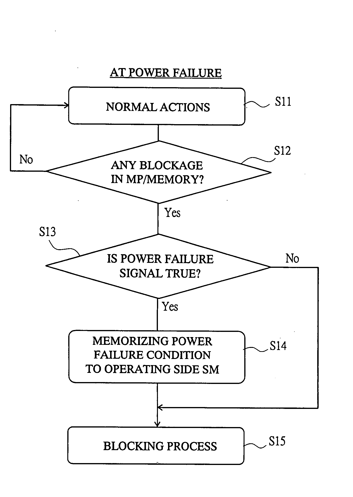
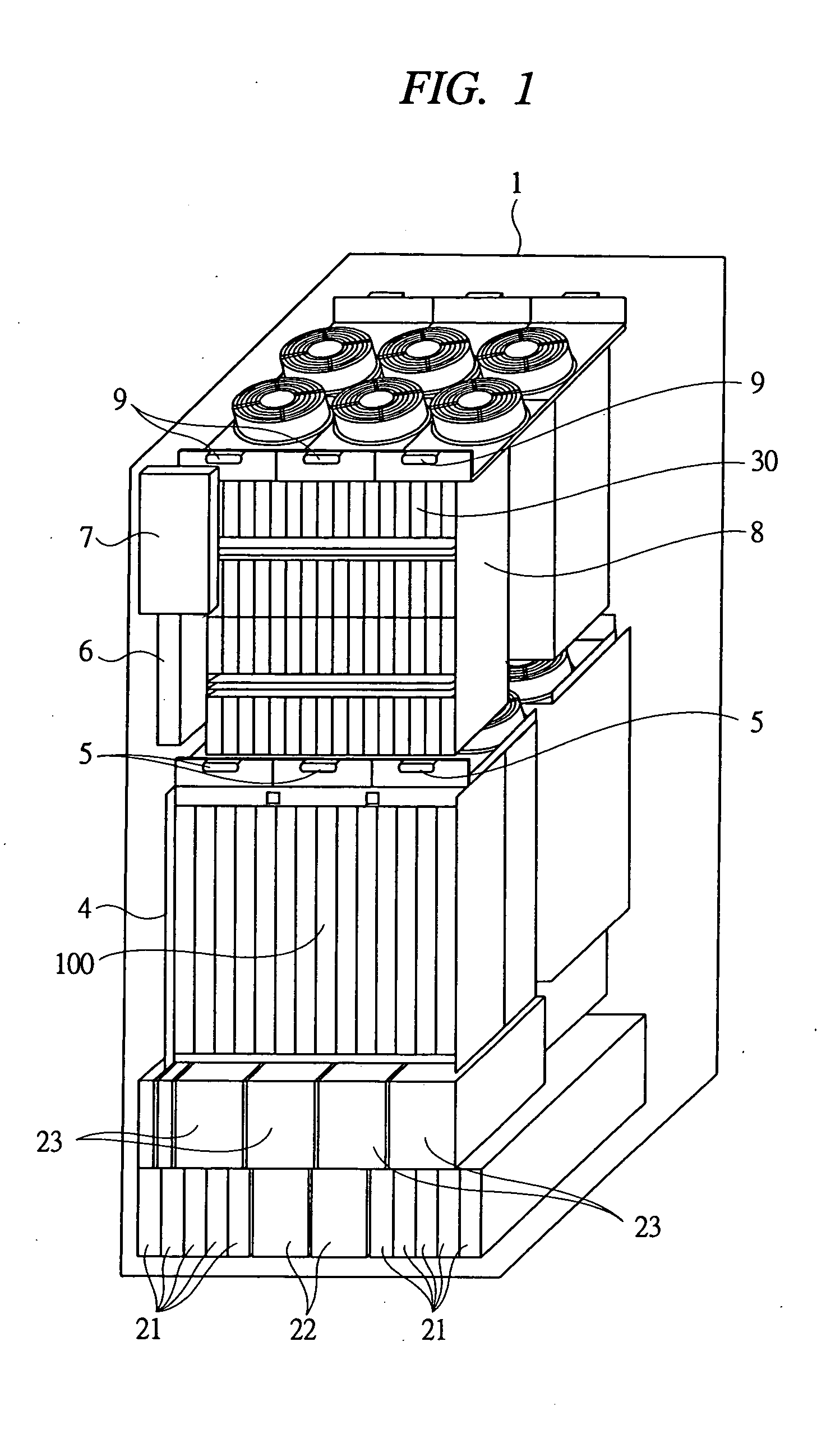
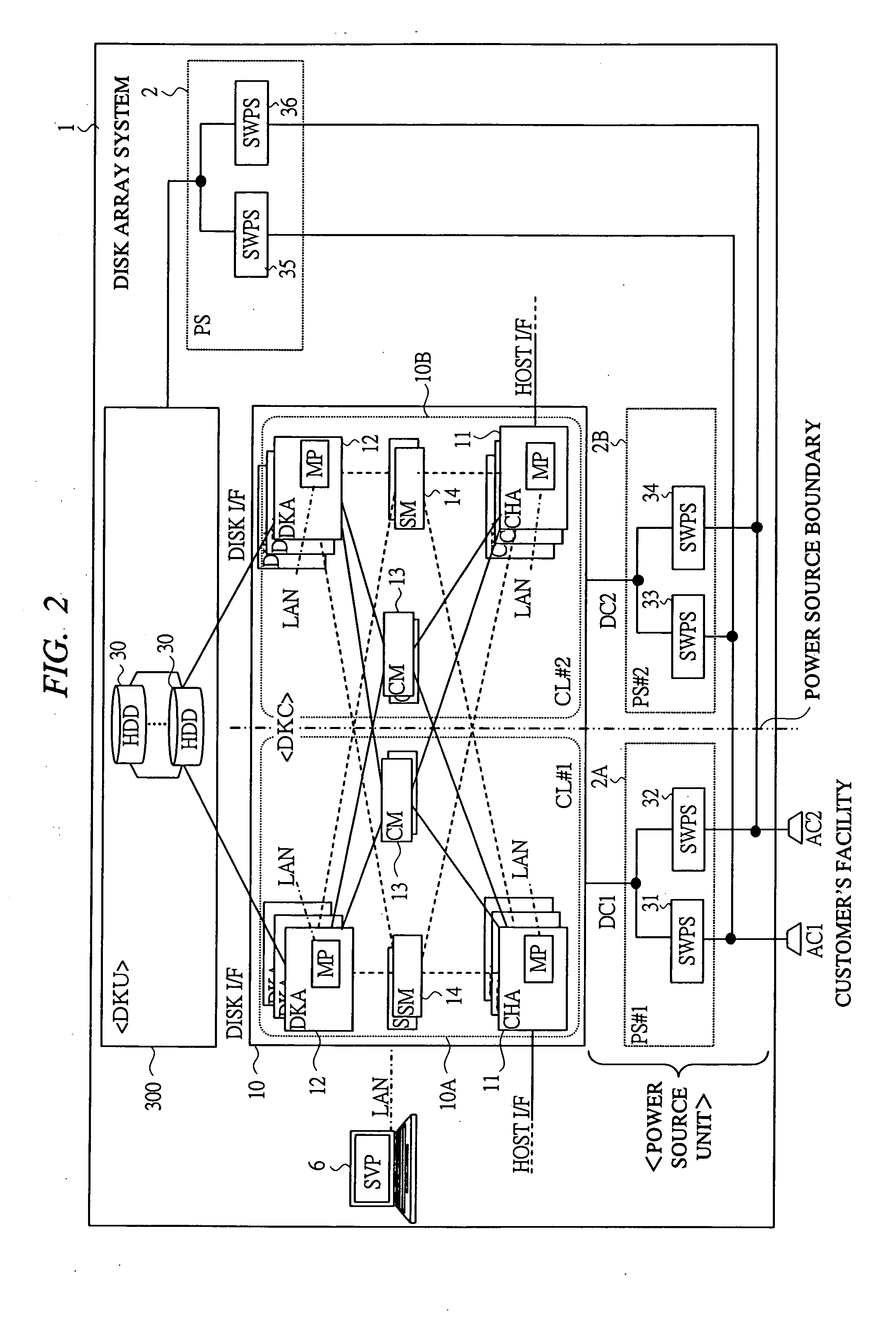
[0040]FIG. 1 through FIG. 6 are figures for explaining a display array device 1 of the first embodiment according to the present invention. In the first embodiment, in a duplexed structure of DKCs and power source units, as the first control, power failure control and power recovery control are carried out, to cope with operation stop of clusters of DKCs at occurrence of a relatively long power failure. In the power failure control, at blockage processing to the portion of the cluster that has stopped first, by the cluster that stops thereafter owing to the difference in stop time, power failure condition is recognized on the basis of the power failure judgment, and condition information where the occurrence of the blocked condition and the power failure condition are related together with each other is stored into a nonvolatile memory. Then, in the power recovery control, among both the clusters that have restarted, when the cluster at the side in normal condition recognizes that t...

second embodiment

[0117]FIG. 7 and FIG. 8 are figures for explaining a disk array system 1 according to a second embodiment of the present invention. In the second embodiment, in a duplexed structure of DKCs and power source units, as a second control, power failure control and power recovery control corresponding to one cluster operation stop of DKC at occurrence of a short power failure is carried out. In the power failure control, at the blocking process on the portion of the cluster that stops by the cluster that does out stop and continues operation, power failure condition is recognized on the basis of power failure judgment, and condition information in which the occurrence of blocked condition and power failure condition are interrelated is stored in a nonvolatile memory. Then, in the power recovery control, the cluster of the side that continues operation periodically carries out access of action soundness check to the portion of blocked condition in the cluster at the side that has stopped,...

third embodiment

[0136]FIG. 9A and FIG. 9B are figures for explaining a disk array system 1 according to a third embodiment of the present invention, and are block diagrams showing a second structure example of power source units and clusters, concerning the control at power failure and recovery in the third embodiment. FIG. 9A especially shows the second structure example concerning means for judging power condition, and FIG. 9B shows a detailed structure of a power failure judging unit 103B therein. In the disk array system 1, means for judging power failure condition is structured mainly with the circuit of the AC connected power failure judging unit 103B. In the circuit structure of the third embodiment, a function to execute one or both of the first and second controls shown in the first and second embodiments is arranged.

[0137] In FIG. 9A, the present structure is a structure where one power failure judging unit 103B is arranged between input AC power sources (AC1 and AC2) and respective CLs ...


PUM


Abstract

In a disk array system, multiplexed clusters and multiplexed power source units for supplying power sources to the respective clusters are arranged. Each cluster has a power failure judging unit for judging the power source condition of other cluster. In response to a case where one cluster stops its operation first owing to a power failure, at the power failure, for example, MP of the cluster blocks the portion of the other cluster, and judges the power source condition of the other cluster on the basis of a signal from the power failure judging unit, and records power failure information showing the power source condition to a memory. At power recovery, if the cluster recognizes that the portion in blocked condition of the other cluster is in blockage owing to the power failure, the cluster recovers the portion.

Description

CROSS-REFERENCE TO RELATED APPLICATION [0001] The present application claims priority from Japanese Patent Application No. JP 2005-44960 filed on Feb. 22, 2005, the content of which is hereby incorporated by reference into this application. TECHNICAL FIELD OF THE INVENTION [0002] The present invention relates to a disk array system that has a storage device such as a hard disk drive (HDD) and a storage control device to control data storing to the storage device (hereinafter, referred to as DKC) and enables RAID control, more specifically, it relates to a technology for recovery at power failure and recovery. BACKGROUND OF THE INVENTION [0003] In a conventional disk array system, a structure having multiplexed DKCs and multiplexed power source units for supplying power source thereto is adopted for securing reliability. For example, a structure may be made so that a DKC is multiplexed, i.e., made into logical clusters (for example, CL1 and CL2), and 2 systems of power source units (...

Claims


Application Information

Patent Timeline
Patent Type & Authority Applications(United States)
IPC IPC(8): G06F1/26
CPCG11B19/04G11B19/08
Inventor FUKUMORI, MITSUO
Owner HITACHI LTD
Why Eureka
Try Eureka