Rack management system, management terminal, configuration retaining apparatus and rack apparatus

a management system and rack technology, applied in the field of rack management systems, can solve problems such as system problems that are problematically inconvenient, the maintenance operator at the site where the racks are disposed cannot easily grasp the accommodating state, and the maintenance operator that is to repair the failed server cannot easily grasp the system, so as to achieve convenient and fast specified, easy to grasp the accommodating state, and improve the effect of maintenan

Inactive Publication Date: 2006-08-24
FUJITSU LTD
View PDF11 Cites 24 Cited by
  • Summary
  • Abstract
  • Description
  • Claims
  • Application Information

AI Technical Summary

Benefits of technology

[0021] Since, if the maintenance operator confirms the failed apparatus with reference to the corresponding configuration retaining apparatus, the fact that the maintenance operator has confirmed the failed apparatus is sent from the corresponding configuration retaining apparatus to the management terminal through the communication network, the management operator can confirm that the fact that the maintenance operator has confirmed the failed apparatus (in other words, confirms that the maintenance operator is about to start repairing and maintenance, or has completed repairing and maintenance) and maintainability is therefore improved.
[0022] Since the configuration information of the accommodation positions and the sizes of apparatuses accommodated in each rack is sent from the corresponding configuration retaining apparatus to the management terminal through the communication network, the management terminal can display an image representing an accommodating state of apparatuses of each rack based on the received configuration information. As a consequence, in an environment exemplified by a data center that deals with a large number of apparatuses (electronic devices) such as servers, since an accommodation state of the apparatuses accommodated in a number of racks are displayed in the form of images on the management terminal, the management operator can easily grasp the accommodating state.
[0023] Especially, since when an apparatus breaks down, the management terminal displays information concerning the failed apparatus or emphasizes the failed apparatus in the image, the management operator can obtain information of the accommodation position of the failed apparatus in the form of image in addition to text information, the management operator can surely grasp the accommodation position of the failed apparatus accurately and immediately, so that the failed apparatus can be easily and quickly specified.
[0024] Further, if a configuration retaining apparatus serves as one of the apparatuses accommodated in a rack, there is no need to newly create a special rack provided with a configuration retaining apparatus whereupon an existing rack can be used for the present invention without being modified and the rack management system of the present invention can be realized with ease at low cost.

Problems solved by technology

When a server (electronic device) accommodated in a rack breaks down, the manager of electronic devices can specify the broken server with reference to the management terminal, but a maintenance operator at the site where the racks are disposed can not easily do so.
However, in the above conventional specifying manner, unless the management terminal is disposed near to a rack that accommodates the failed server, it is difficult for the maintenance operator that is to repair the failed server to grasp in which position in which rack the failed server is accommodated because the maintenance operator cannot specify the failed server simply by referring to racks.
Such a system has been problematically inconvenient.
Even if technologies of Patent references 1 and 2 are applied to a system including a large number of servers exemplified above (in this case, regarding each server as a substrate), these techniques only have to take the same measurement as that mentioned above in an event of failure occurrence in a server (substrate) and therefore the above problems cannot be solved.

Method used


Image

  • Rack management system, management terminal, configuration retaining apparatus and rack apparatus
  • Rack management system, management terminal, configuration retaining apparatus and rack apparatus
  • Rack management system, management terminal, configuration retaining apparatus and rack apparatus

Examples


Embodiment Construction

[0029] A preferred embodiment of the present invention will now be described with reference to the accompanying drawings.

[0030] (1) Configuration of a Preferred Embodiment:

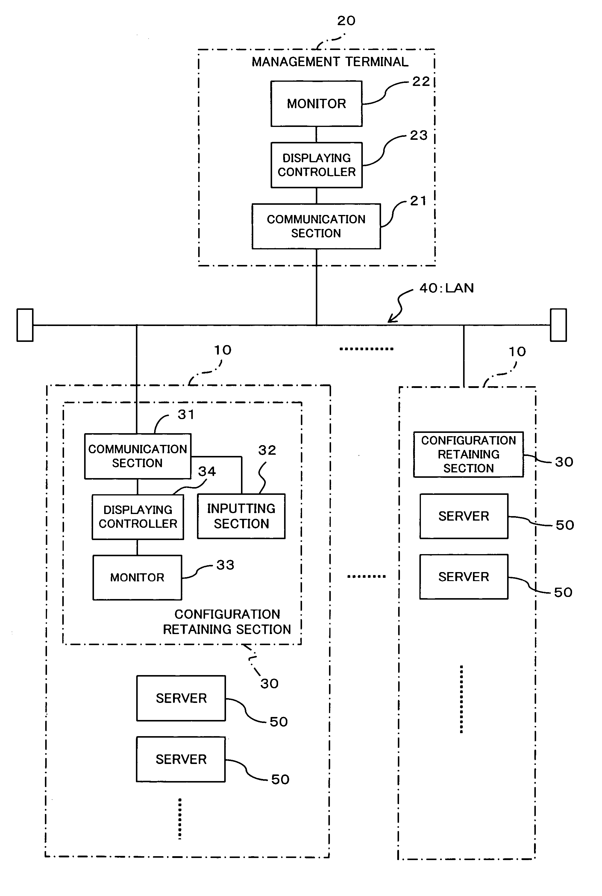
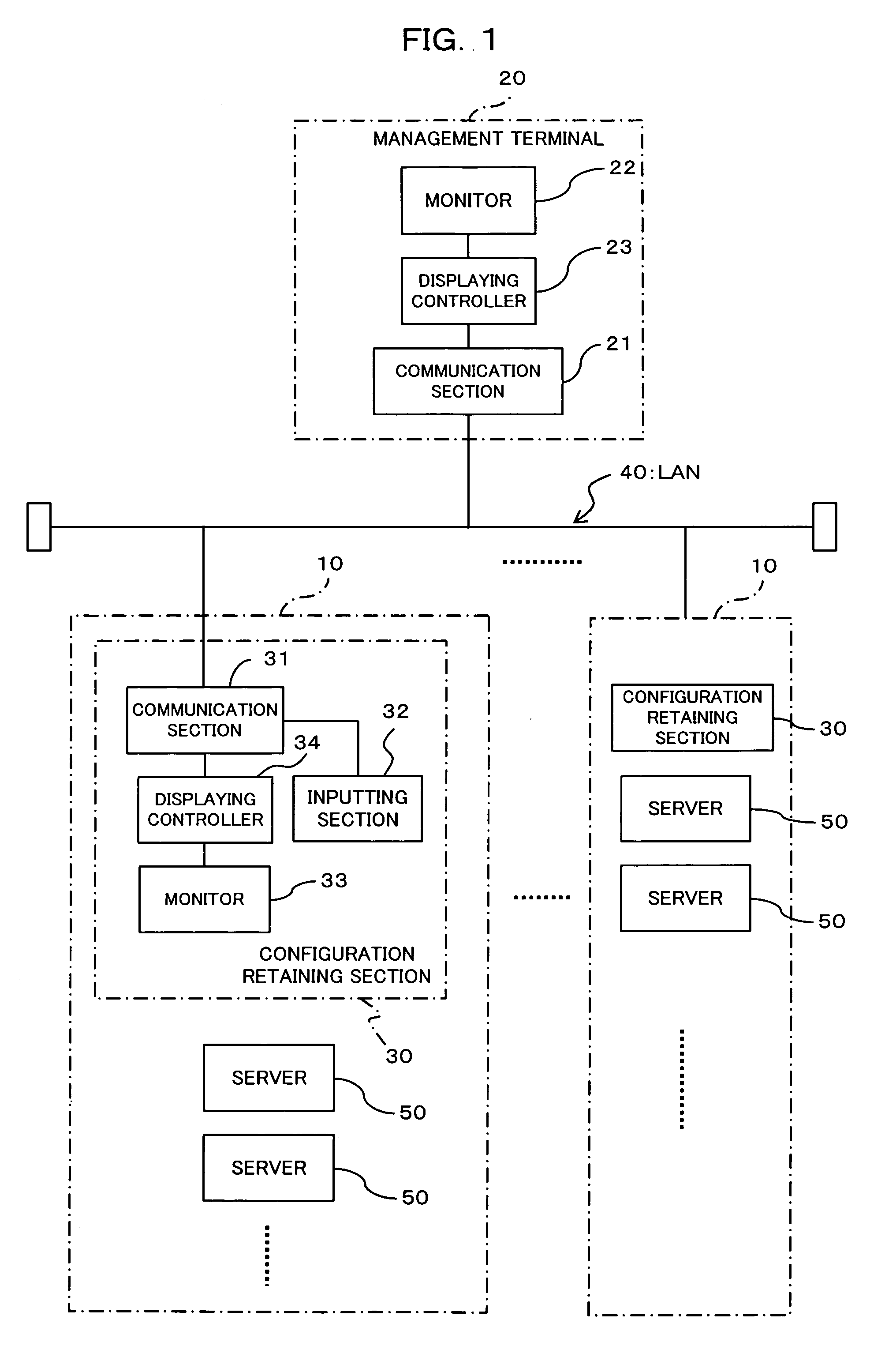
[0031] As shown in FIG. 1, a rack management system according to the present embodiment comprises a number of racks 10, a management terminal 20, a number of configuration retaining apparatuses 30 provided one for each of the racks 10, and a LAN (Local Area Network) 40.

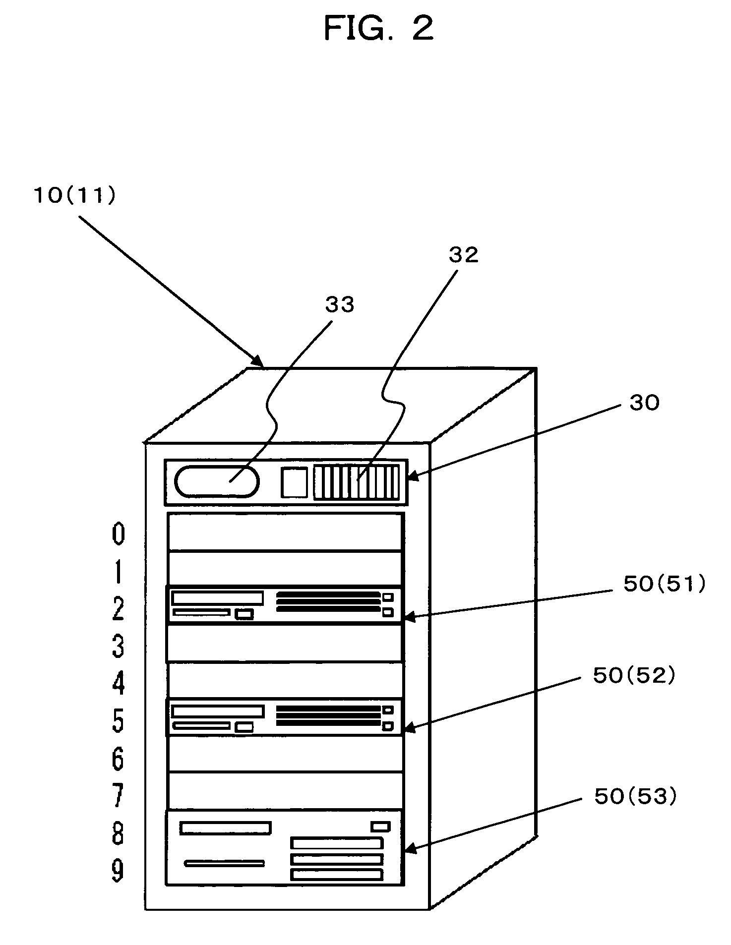
[0032] Here, each rack (rack apparatus) 10 can accommodate two or more apparatuses (electronic devices) and takes the form of a 19-inch rack that can accommodate up to ten 1U servers 50 as shown in FIG. 2. Further as shown in FIG. 2, configuration retaining apparatus 30 is placed at the top of the case of each rack 10. As mentioned above, a rack 10 of the present embodiment has ten rows that are capable of accommodating ten 1U servers 50. For easily specifying an accommodation position of each server 50 in a rack 10 with reference to numerical da...


PUM


Abstract

In order to rapidly specify a failed apparatus in such an environment at a data center that handles a large number of electronic devices exemplified by servers with ease so that maintainability can be improved, when each configuration retaining apparatus receives information concerning an apparatus specified by a management terminal, a configuration retaining apparatus displaying controller displays the information concerning the specified apparatus on the configuration retaining apparatus monitor.

Description

BACKGROUND OF THE INVENTION [0001] 1. Field of the Invention [0002] The present invention relates to a rack management system for managing electronic devices, such as servers and network devices, accommodated in a number of racks, a management terminal, a configuration retaining apparatus, and a rack apparatus to be used for accommodating these servers and electronic devices. [0003] 2. Description of the Related Art [0004] In a general data center that uses a large number of electronic devices, such as servers and network devices, the electronic devices are accommodated in a number of racks to carry out operation. In such an environment, racks are usually disposed remotely from the management terminal. When a server (electronic device) accommodated in a rack breaks down, the manager of electronic devices can specify the broken server with reference to the management terminal, but a maintenance operator at the site where the racks are disposed can not easily do so. Therefore, in orde...

Claims


Application Information

Patent Timeline
Patent Type & Authority Applications(United States)
IPC IPC(8): G06F11/00G06F11/32
CPCG06F11/328
Inventor KAWASE, HIROAKI
Owner FUJITSU LTD
Why Eureka
Try Eureka