Method and device for full thickness resectioning of an organ

a full-thickness resection and organ technology, applied in the direction of surgical staples, surgical forceps, paper/cardboard containers, etc., can solve the problems of long recovery time, partial or complete loss of mobility, and painful incisions,

Inactive Publication Date: 2006-08-31
BOSTON SCI SCIMED INC
View PDF8 Cites 122 Cited by
  • Summary
  • Abstract
  • Description
  • Claims
  • Application Information

AI Technical Summary

Problems solved by technology

For example, several known resection devices and procedures requires at least one incision in an area near the portion of the organ to be excised for access to the lesion or treatment site (because, for example, the resectioning device may lack steering and / or viewing capabilities).
Of course, these incisions are painful and may involve a partial or entire loss of mobility while recuperating from the incision, in addition to recovering from the tubular resectioning procedure itself.
In addition, the time required to recover from such a procedure is often longer than for procedures which do not require incisions.
Thus, this type of resectioning procedure involves the drawbacks mentioned above in regard to procedures requiring invasive incisions.
In addition, the separation of the organ into two segments creates the risk of spillage of non-sterile bowel contents into the sterile body cavity, which can cause severe infection and possibly death.
This arrangement limits the effective operating range of the device as the bending of the shaft into the desired shape before insertion and the rigidity of the shaft once bent require the physician to ascertain the location of the organ section to be removed before insertion, and deform the shaft accordingly.
Furthermore, the rigidity of the shaft makes it difficult to reach remote areas in the organ—particularly those areas which must be reached by a winding and / or circuitous route (e.g., sigmoid colon).

Method used


Image

  • Method and device for full thickness resectioning of an organ
  • Method and device for full thickness resectioning of an organ
  • Method and device for full thickness resectioning of an organ

Examples


first embodiment

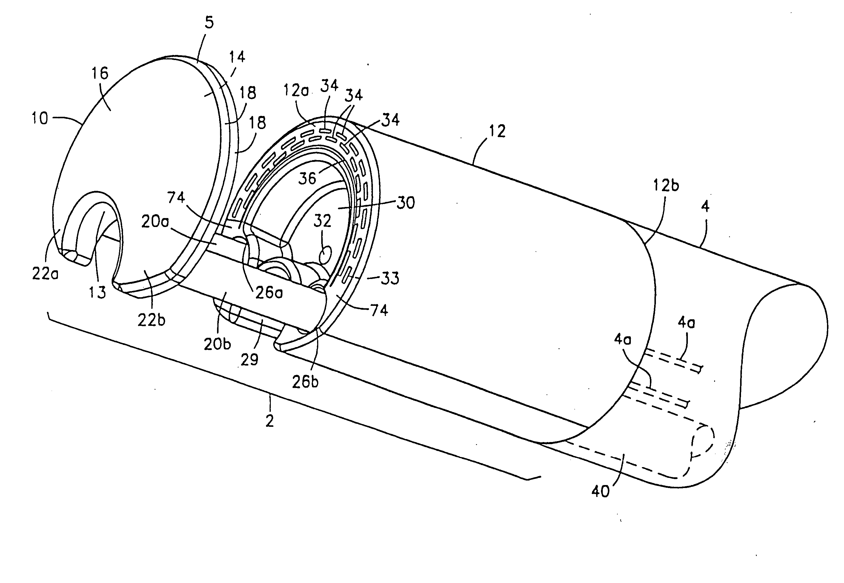
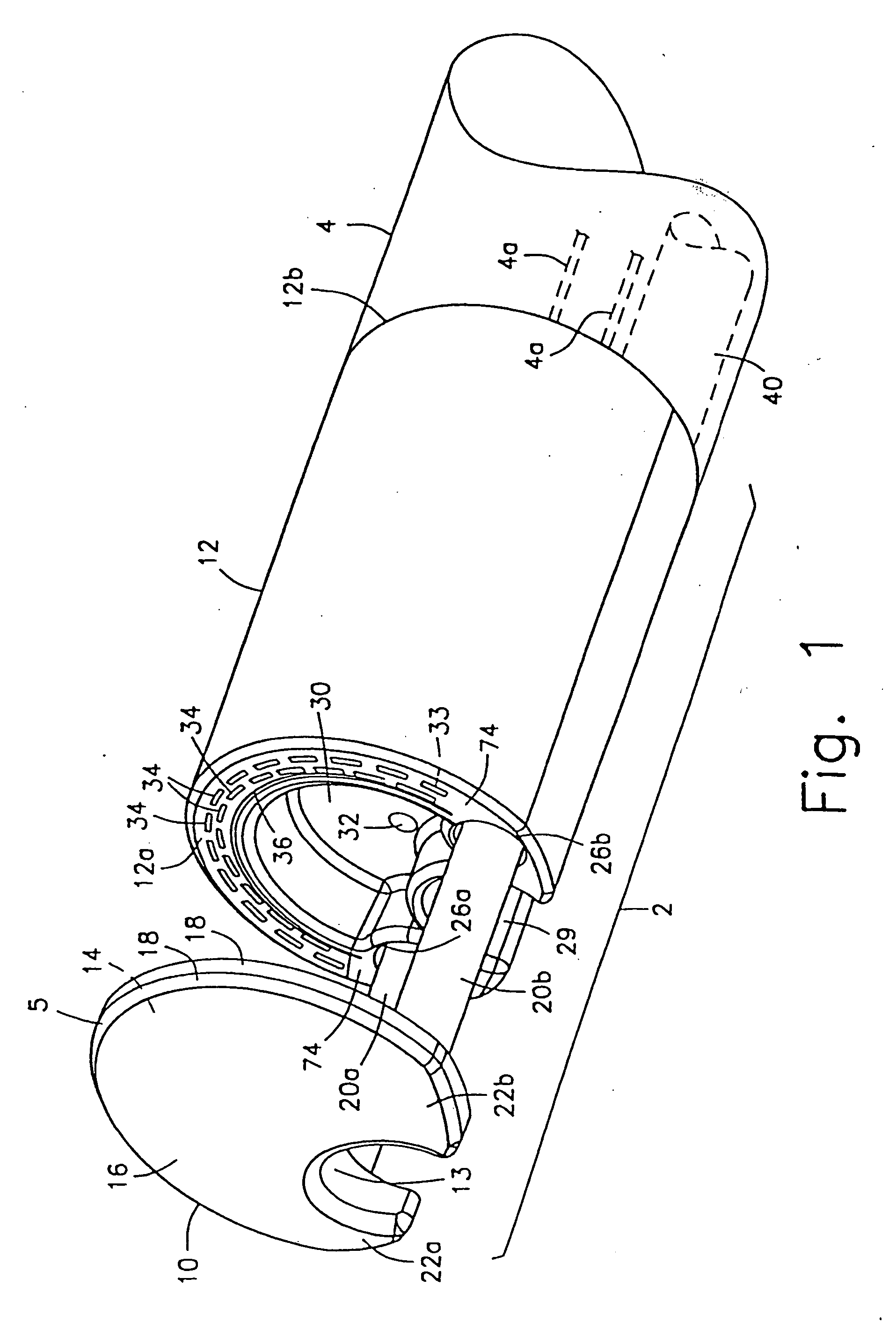
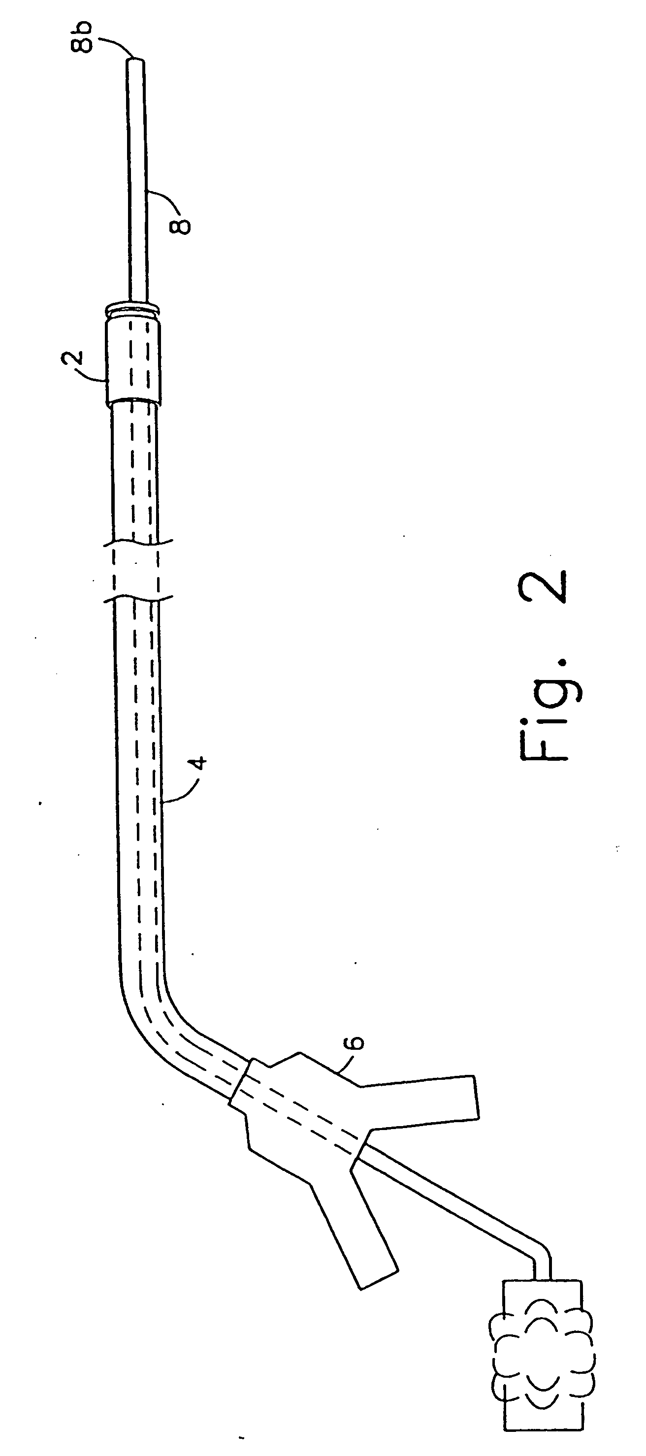
[0043] As shown in FIGS. 1 and 2, an apparatus according to the present invention comprises a working head assembly 2 which may preferably be connected to a distal end 4a of a sheath 4. The proximal end 4b of the sheath 4 may preferably be connected to a control handle 6.

[0044] In operation, the entire apparatus is mounted onto an endoscope 8 by passing the endoscope 8 through the control handle 6, the sheath 4, and the working head assembly 2, as shown in FIG. 2. The endoscope 8 is then inserted into a body orifice to locate a lesion in the tubular organ under visual observation (usually while insufflating the organ). Once the lesion has been located, the working head assembly 2 and the sheath 4 are slidably advanced along the endoscope 8 into the tubular organ until the working head assembly 2 is in a desired position adjacent to the lesion. Those skilled in the art will understand that in an alternative embodiment, the working head assembly 2 may also be detachably coupled to a d...

second embodiment

[0077]FIG. 11 shows a device according to the present invention in which like reference numerals identify the same elements.

[0078] The anvil member 10 of this embodiment preferably has a substantially circular or elliptical cross-section and is gradually tapered from the proximal face 14 to its distal end 16, forming a bullet-like structure. This tapered shape allows the device to be more easily inserted into the patient's body as the distal end 16 has a smaller cross-sectional size than in the first embodiment. Those skilled in the art will understand that the anvil member 10 may have other tapered shapes besides a bullet-like structure without departing from the scope of the present invention.

[0079] Instead of providing the cut-out 13 shown in the first embodiment to receive the endoscope 8 therein, a substantially cylindrical first endoscope lumen 13 extends axially through the center of the anvil member 10. The distal end 16 of the anvil member 10 may preferably have a beveled ...

third embodiment

[0084]FIG. 12 shows a device according to the present invention. The proximal face 14 of the anvil member 10 of this embodiment has a cross-section similar to the crescent-shaped cross-section of the anvil member 10 of the device of FIG. 1. Thus, the anvil member 10 has two horns 22a and 22b formed on either side of a cut-out 13 which extends axially through the anvil member 10 from the proximal face 14 to the distal end 15 to receive the endoscope 8 therein. As with the device of FIG. 11, the cross-sectional size of the anvil member 10 diminishes in overall size from a maximum at the proximal face 14 to a minimum size at the distal end 15, and the horns 22a and 22b become less pronounced from the proximal face 14 to the distal end 15. In a side view, the anvil member 10 becomes gradually tapered from the proximal end 14 to the distal end 16.

[0085] As in the device of FIG. 11, the tapered shape of the anvil member 10 of the device of FIG. 12 allows for easier insertion of the device...


PUM

PropertyMeasurementUnit
diameteraaaaaaaaaa
diameteraaaaaaaaaa
thicknessaaaaaaaaaa

Abstract

Describeed is a full-thickness resection system which includes a control unit coupled to a proximal end of a flexible endoscope. The control unit remains outside of a body when the stapling head is in an operative position within a body lumen. The control unit includes (i) an anvil actuator coupled to an anvil in the stapling head, actuation of the anvil actuator moves the anvil axially relative to a stapling mechanism in the stapling head to compress a folded full-thickness portion of lumenal tissue between the anvil and the stapling mechanism. In addition, the control unit includes (ii) a stapler actuator coupled to the stapling mechanism in the stapling head, actuation of the stapler actuator causing the stapling mechanism to drive staples through the folded lumenal tissue against the anvil. Also, the control unit includes (iii) a tissue cutter actuator coupled to a tissue cutter in the stapling head, actuation of the tissue cutter actuator causing the tissue cutter to resect portions of the folded lumenal tissue.

Description

CLAIM OF PRIORITY [0001] This application is a Continuation application of U.S. patent application Ser. No. 10 / 251,192 filed Sep. 19, 2002 entitled “Method and Device for Full thickness Resectioning of an Organ” which is divisional application of U.S. patent application Ser. No. 10 / 055,306 filed Jan. 23, 2002 (U.S. Pat. No. 6,478,210) which is a Continuation of U.S. patent application Ser. No. 09 / 813,944 filed Mar. 22, 2001 (U.S. Pat. No. 6,343,731) which is a Continuation of U.S. patent application Ser. No. 09 / 694,894 filed Oct. 25, 2000 (U.S. Pat. No. 6,241,140). All applications are expressly incorporated herein, in their entirety, by reference.FIELD OF THE INVENTION [0002] The present invention relates to full thickness resection devices for performing localized resections of lesions in tubular organs, particularly the colon. BACKGROUND INFORMATION [0003] A resection procedure involves excising a portion of an organ, approximating the surrounding tissue together to close up the ...

Claims


Application Information

Patent Timeline
Patent Type & Authority Applications(United States)
IPC IPC(8): A61B17/04A61B17/08A61B17/00A61B17/072A61B17/28A61B19/00
CPCA61B1/00087A61B17/072A61B17/07207A61B17/29A61B17/295A61B2017/00353A61B2017/07214A61B2017/07221A61B2017/2905A61B2017/2927A61B2019/308A61B2019/5206A61B2090/038A61B2090/306
Inventor ADAMS, RONALD D.SULLIVAN, ROY H. IIINUNEZ, GEORGE A.MAIN, LAUREN O.KRATSCH, PETER K.KORTENBACH, JURGEN A.SOLAR, MATTBUESS, GERHARD F.SCHURR, MARC O.
Owner BOSTON SCI SCIMED INC
Why Eureka
Try Eureka