Vacuum ultraviolet reflectometer having collimated beam
What is AI technical title?
AI technical title is built by Patsnap AI team. It summarizes the technical point description of the patent document.
a technology of ultraviolet reflectometer and collimator, which is applied in the field of optical metrology, can solve the problems of not being able to reference the collected data, unable to meet the requirements of manufacturing environments, so as to achieve faster convergence, improve the degree of constraint, and improve the effect of accuracy
Inactive Publication Date: 2006-08-31
BRUKER TECH LTD
View PDF44 Cites 18 Cited by
Summary
Abstract
Description
Claims
Application Information
AI Technical Summary
This helps you quickly interpret patents by identifying the three key elements:
Problems solved by technology
Method used
Benefits of technology
Benefits of technology
[0011] An objective of the current invention is to provide the semiconductor manufacturing industry with a reliable optical metrology tool that is capable of characterizing semiconductor devices incorporating thinner layers and new complicated materials. Any fitting algorithms employed by a user of the instrument may achieve faster convergence and more accurate results by taking full advantage of the higher level of constraint afforded by a data set comprised of two or more spectral regions. This instrument will be non-contact and non-destructive and will make use of broad band reflectance data.
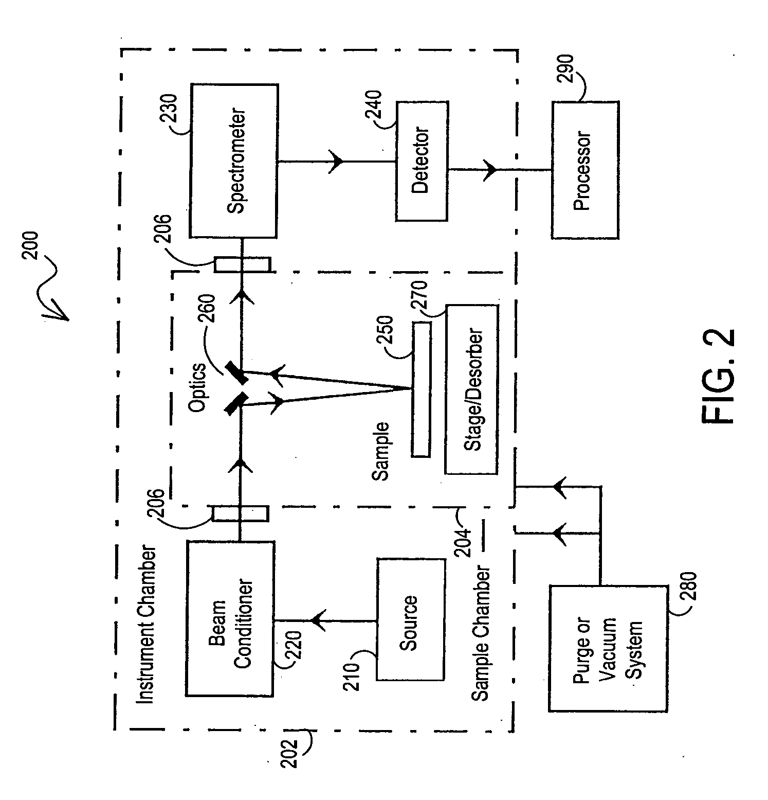
[0012] The instrument will be optimized for operation in a first spectral region and capable of performing well in at least one other spectral region. A selection of sources and detectors for use in separate spectral regions are incorporated within an optical module in the instrument that permits their selection. Additionally, this module contains common delivery and collection optics to enable measurements in separate spectral regions to be collected using similar spot properties. Furthermore, the invention employs a serial collection approach whereby data from separate spectral regions is collected sequentially to avoid stray light complications.
[0013] In one embodiment a spectroscopy system is provided which is optimized for operation in a first spectral region and capable of performing well in at least one other. The system is designed such that no moving optical elements (apart from shutters) are involved in the collection of data from the first spectral region. Additionally, the system incorporates an optical module which presents selectable sources and detectors optimized for separate spectral regions. As well, the optical module provides common delivery and collection optics to enable measurements in separate spectral regions to be collected using similar spot properties. The module also provides a means of quickly referencing measured data so as to ensure that highly repeatable results are achieved.
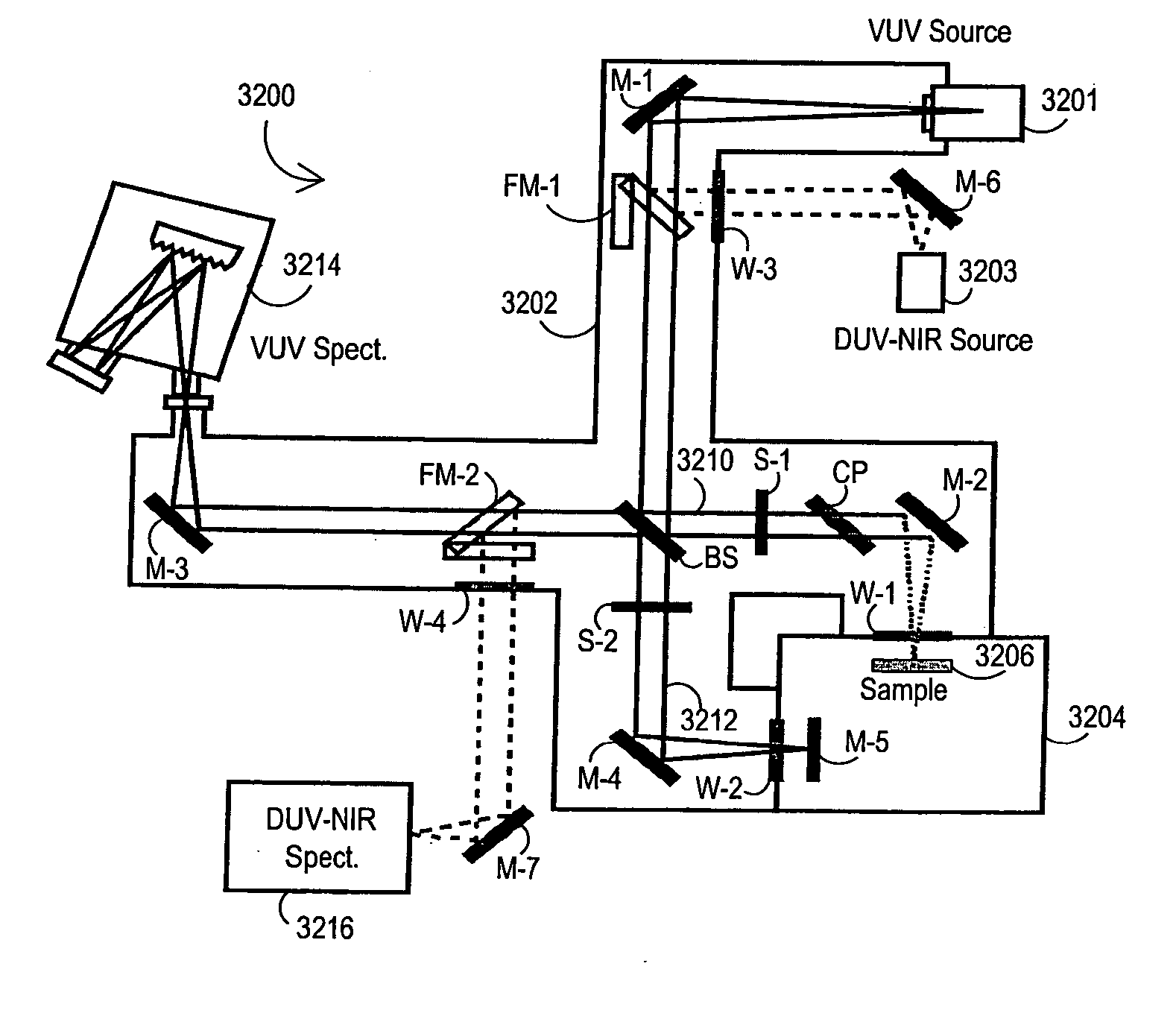
[0014] In another embodiment a spectroscopy system is provided which is optimized for operation in the VUV and capable of performing well in the DUV-NIR. Additionally, the system incorporates an optical module which presents selectable sources and detectors optimized for use in the VUV and DUV-NIR. As well, the optical module provides common delivery and collection optics to enable measurements in both spectral regions to be collected using similar spot properties. The module also provides a means of quickly referencing measured data so as to ensure that highly repeatable results are achieved. The module further provides a controlled environment between the VUV source, sample chamber and VUV detector which acts to limit in a repeatable manner the absorption of VUV photons. The use of broad band data sets which encompass VUV wavelengths, in addition to the DUV-NIR wavelengths enables a greater variety of materials to be meaningfully characterized. Array based detection instrumentation may be exploited to permit the simultaneous collection of larger wavelength regions.
Problems solved by technology
The push towards thinner layers and the introduction of new complicated materials has challenged the sensitivity of such instrumentation.
This approach is often time consuming and not well suited to manufacturing environments like those encountered in the semiconductor industry.
Interferometers are widely used in the infrared spectral region to collect data over a wide range of wavelengths; however, these instruments are not commonly employed in the VUV since optical and mechanical tolerances of the instrument scale with wavelength and are difficult to satisfy in this spectral region.
Although this system enables efficient measurements to be performed over a number of spectral sub-bands, it provides no means of referencing the collected data.
Hence, while signal throughput may be high, system repeatability may be quite poor.
Method used
Image
Click on the blue label to locate the original text in one second.
Reading with bidirectional positioning of images and text.
Examples
Embodiment Construction
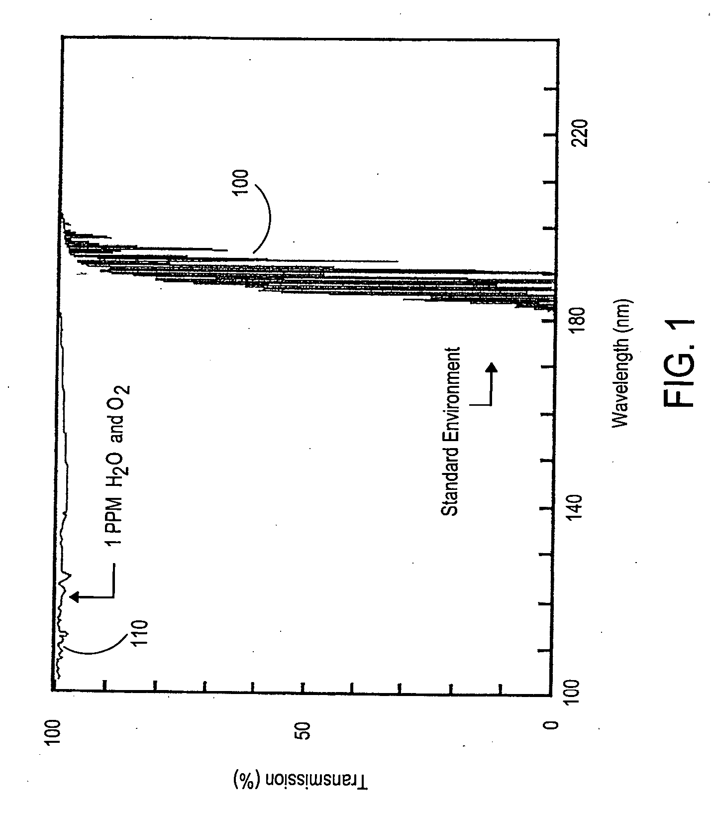
[0061] To enhance the sensitivity of optical metrology equipment for challenging applications it is desirable to extend the range of wavelengths over which such measurements are performed. Specifically, it is advantageous to utilize shorter wavelength (higher energy) photons extending into, and beyond, the region of the electromagnetic spectrum referred to as the vacuum ultra-violet (VUV). Historically there has been relatively little effort expended on the development of optical instrumentation designed to operate at these wavelengths, owing to the fact that VUV (and lower) photons are strongly absorbed in standard atmospheric conditions. Vacuum ultra-violet (VUV) wavelengths are generally considered to be wavelengths less than deep ultra-violet (DUV) wavelengths. Thus VUV wavelengths are generally considered to be wavelengths less than about 190 nm. While there is no universal cutoff for the bottom end of the VUV range, some in the field may consider VUV to terminate and an extrem...
PUM
Property
Measurement
Unit
wavelengths
aaaaa
aaaaa
near-infrared wavelengths
aaaaa
aaaaa
wavelengths
aaaaa
aaaaa
Abstract
A spectroscopy system is provided which is optimized for operation in the VUV region and capable of performing well in the DUV-NIR region. Additionally, the system incorporates an optical module which presents selectable sources and detectors optimized for use in the VUV and DUV-NIR. As well, the optical module provides common delivery and collection optics to enable measurements in both spectral regions to be collected using similar spot properties. The module also provides a means of quickly referencing measured data so as to ensure that highly repeatable results are achieved. The module further provides a controlled environment between the VUV source, sample chamber and VUV detector which acts to limit in a repeatable manner the absorption of VUV photons. The use of broad band data sets which encompass VUV wavelengths, in addition to the DUV-NIR wavelengths enables a greater variety of materials to be meaningfully characterized. Array based detection instrumentation may be exploited to permit the simultaneous collection of larger wavelength regions.
Description
CROSS-REFERENCE TO RELATED APPLICATIONS [0001] This application is a continuation of U.S. patent application Ser. No. 10 / 909,126 filed on Jul. 30, 2004 which is a continuation-in-part of (1) U.S. patent application Ser. No. 10 / 669,030 filed on Sep. 23, 2003 which claims priority to Provisional Patent Application Nos. 60 / 440,434, 60 / 440,435, and 60 / 440,443 all filed Jan. 16, 2003; (2) U.S. patent application Ser. No. 10 / 668,642 filed on Sep. 23, 2003 which claims priority to Provisional Patent Application Nos. 60 / 440,434, 60 / 440,435, and 60 / 440,443 all filed Jan. 16, 2003; and (3) U.S. patent application Ser. No. 10 / 668,644 filed on Sep. 23, 2003 which claims priority to Provisional Patent Application Nos. 60 / 440,434, 60 / 440,435, and 60 / 440,443 all filed Jan. 16, 2003; the disclosures of which are each expressly incorporated herein by reference.BACKGROUND OF THE INVENTION [0002] The present invention relates to the field of optical metrology. More specifically it provides a means by ...
Claims
Application Information
Patent Timeline
Application Date:The date an application was filed.
Publication Date:The date a patent or application was officially published.
First Publication Date:The earliest publication date of a patent with the same application number.
Issue Date:Publication date of the patent grant document.
PCT Entry Date:The Entry date of PCT National Phase.
Estimated Expiry Date:The statutory expiry date of a patent right according to the Patent Law, and it is the longest term of protection that the patent right can achieve without the termination of the patent right due to other reasons(Term extension factor has been taken into account ).
Invalid Date:Actual expiry date is based on effective date or publication date of legal transaction data of invalid patent.
Patent Type & AuthorityApplications(United States)

