Lorentz actuator for miniature camera

a miniature camera and actuator technology, applied in the field of electric motors, can solve problems such as misalignment of optical elements, and achieve the effect of reducing undesirable non-linear (rotational) movemen

Inactive Publication Date: 2006-08-31
SIIMPEL
View PDF12 Cites 10 Cited by
  • Summary
  • Abstract
  • Description
  • Claims
  • Application Information

AI Technical Summary

Benefits of technology

[0011] Systems and methods for providing actuators suitable for use in portable electronic devices, such as the cameras of cellular telephones, are disclosed. For example, in accordance with an embodiment of the present invention, an actuator for a miniature camera comprises a plurality of magnets and a plurality of coils disposed generally symmetrically with respect to the magnets. The magnets and the coils can be configured so as to effect linear movement due to a Lorentz force generated therebetween. The magnets and coils can further be configured so that the force generated by the actuator is generally proportional to the current through the coils over the range of travel of the actuator. The magnets and coils are further configured so as to mitigate undesirable non-linear (rotational) movement. Such non-linear movement can result in misalignment of the optical elements.
[0012] More particularly, one or more magnets and two or more coils can be used according to one or more embodiments of the present invention. Alternatively, one or more coils and two or more magnets can be so used. Multiple magnets and coils can be configured to enhance the uniformity of magnetic flux through the coils and to maximize the force provided by the actuator, subject to geometric constraints. In either instance, symmetry is provided that tends to mitigate non-linear movement. Regardless of the number of magnets used, two outboard flux guides can optionally be configured so as to minimize a weight thereof while enhancing the strength and uniformity of flux through the coils and while mitigating undesirable fringing magnetic fields of the actuator. Inboard flux guides can also optionally be used. Either one of the magnets or the coils can be configured to move while the other one thereof stays generally stationary, when current flows through the coils.
[0013] The use of such an actuator provides sufficient force to move the optical elements of a miniature camera, for example, so as to facilitate such features as variable focus, zoom, and image stabilization. This can be accomplished while maintaining the volume and weight of the camera within acceptable limits.

Problems solved by technology

Such non-linear movement can result in misalignment of the optical elements.

Method used


Image

  • Lorentz actuator for miniature camera
  • Lorentz actuator for miniature camera
  • Lorentz actuator for miniature camera

Examples


Embodiment Construction

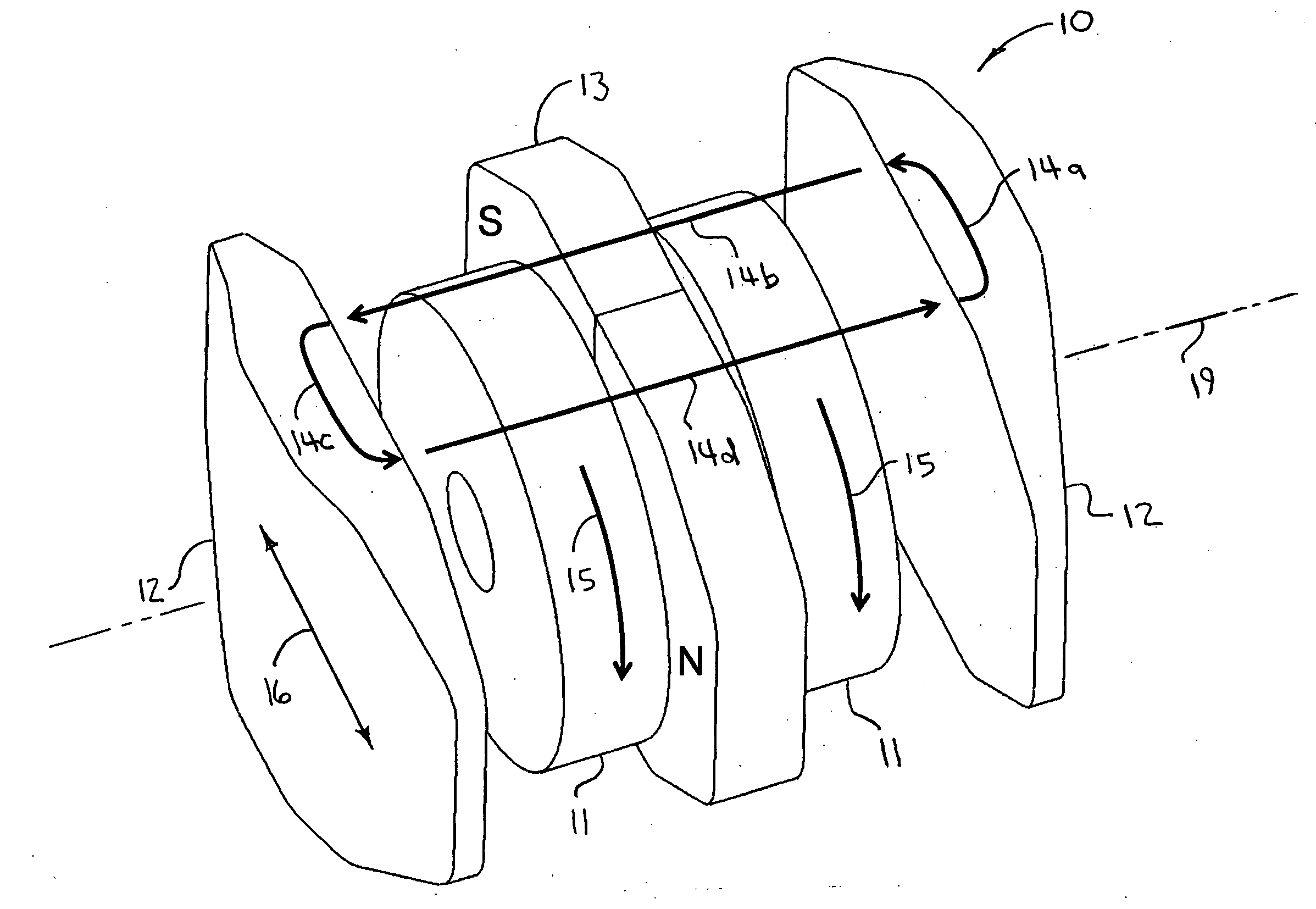
[0031] A method and system for moving miniature components, such as the optical components of a camera for a cellular telephone, uses the Lorentz force to effect such movement. As those skilled in the art will appreciate, the Lorentz force is a magnetic force that is perpendicular to both the local magnetic field and the direction of motion of a charged particle (an electron). The magnitude of this force is given by the formula:

F=I×B Leff [0032] where: [0033] F is the force, [0034] I is current, [0035] B is the magnetic field strength, and [0036] Leff is the effective length of the conductor that carries the current I within the magnetic field B.

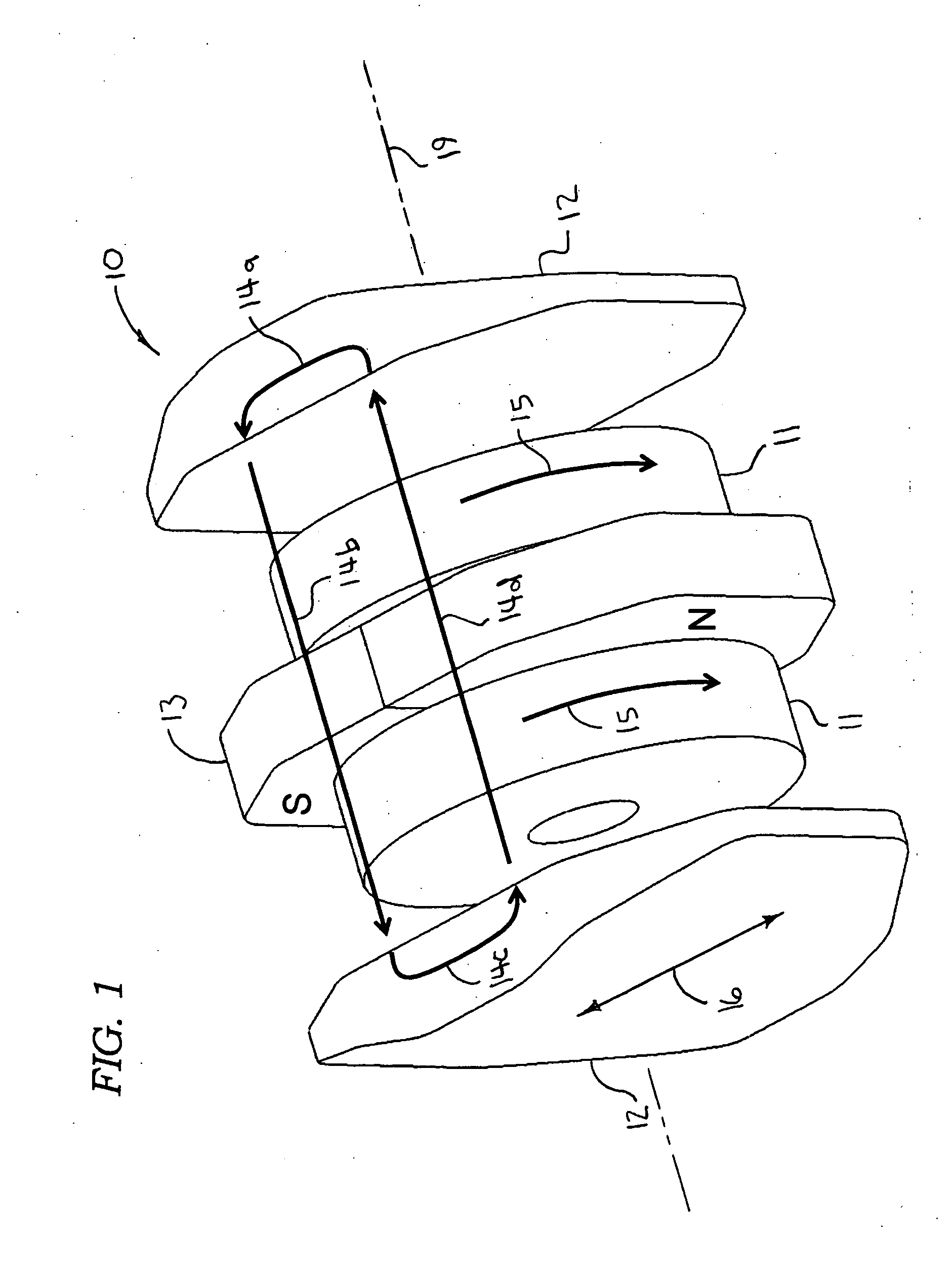
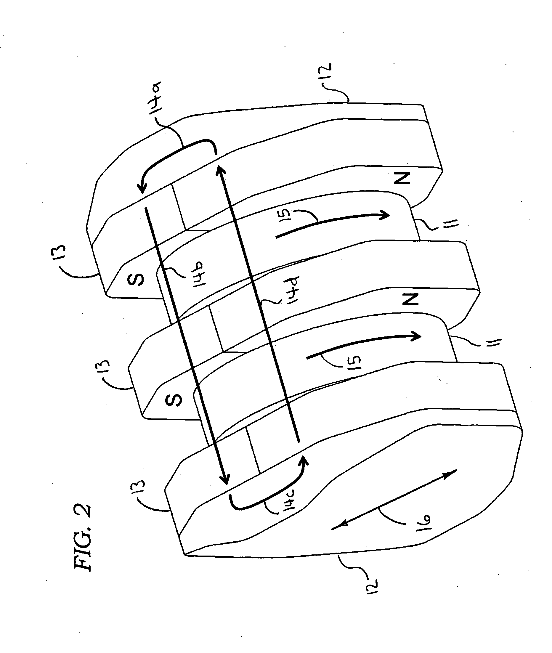
[0037] Referring now to FIG. 1, an exemplary embodiment of the present invention is shown. A Lorentz actuator 10 can be defined by a plurality of coils 11 and at least one magnet 13. Optionally, a plurality of flux guides 12 can be included. Two coils 11 can disposed intermediate two outboard flux guides 12. A single magnet 13 can be dispo...


PUM


Abstract

An actuator for miniature cameras and the like is disclosed. The actuator can comprise a plurality of magnets and a plurality of coils disposed generally symmetrically with respect to the magnets. The magnets and the coils are configured so that they cooperate in order to effect substantially linear movement due to a Lorentz force therebetween. In this manner, undesirable rotational forces can be substantially mitigated. The actuator can be used to effect movement of optical elements to facilitate variable focus, zoom, and / or image stabilization, for example.

Description

PRIORITY CLAIM [0001] This patent application claims the benefit of the priority date of U.S. provisional patent application Ser. No. 60 / 657,261, filed on Feb. 13, 2005 and entitled AUTOFOCUS CAMERA (docket no. M-15826-V1 US) pursuant to 35 USC 119. The entire contents of this provisional patent application are hereby expressly incorporated by reference.TECHNICAL FIELD [0002] The present invention relates generally to electric motors, particularly linear motors, i.e., actuators. The present invention relates even more particularly to a Lorentz actuator for moving optical elements of a miniature camera, such as a miniature camera configured for use in a cellular telephone. BACKGROUND [0003] Miniature cameras are well known. Miniature cameras are widely used in contemporary cellular telephones. They are also used in other devices, such as laptop computers and personal digital assistants (PDA). Miniature cameras can even be used as stand alone devices for such applications as security ...

Claims


Application Information

Patent Timeline
Patent Type & Authority Applications(United States)
IPC IPC(8): G03B3/10
CPCG02B7/102H02K41/0356
Inventor HARRINGTON, DARRELLWANG, GUIQINGUTIERREZ, ROMAN C.CALVET, ROBERT J.
Owner SIIMPEL
Why Eureka
Try Eureka