
Clamping device

a technology of fixing element and device, which is applied in the direction of ligaments, prostheses, osteosynthesis devices, etc., can solve the problems of body being fixed, and achieve the effect of reducing the dimension of the through bor

Active Publication Date: 2006-08-31
SYNTHES USA
View PDF31 Cites 89 Cited by
  • Summary
  • Abstract
  • Description
  • Claims
  • Application Information

AI Technical Summary

Benefits of technology

[0010] The method may further comprise inserting the body into the tapered bore of the receiving member, deforming at least a portion of the body as the thread of the body is screwed into the inner thread of the tapered bore of the receiving member, and reducing the dimension of the through bore so that a fixation element positioned into the through bore is fixed with respect to the body. Upon insertion into the tapered bore, the body may be radially deformed. The construction of the clamping device may enable the clamping device and / or fixation element to be reposition. In particular, the body may be unscrewed / loosened so that the body may be at least partially out of the tapered bore of the receiving member. Thereafter, the clamping device and / or fixation element may be repositioned. The body may then be screwed / inserted back into the tapered bore of the receiving member so that the clamping device may be fixed with respect to the fixation element.

Problems solved by technology

With a fixation element positioned in the through bore, such deformation may results in the body being fixed with respect to the fixation element.

Method used


Image

  • Clamping device
  • Clamping device
  • Clamping device

Examples


Embodiment Construction

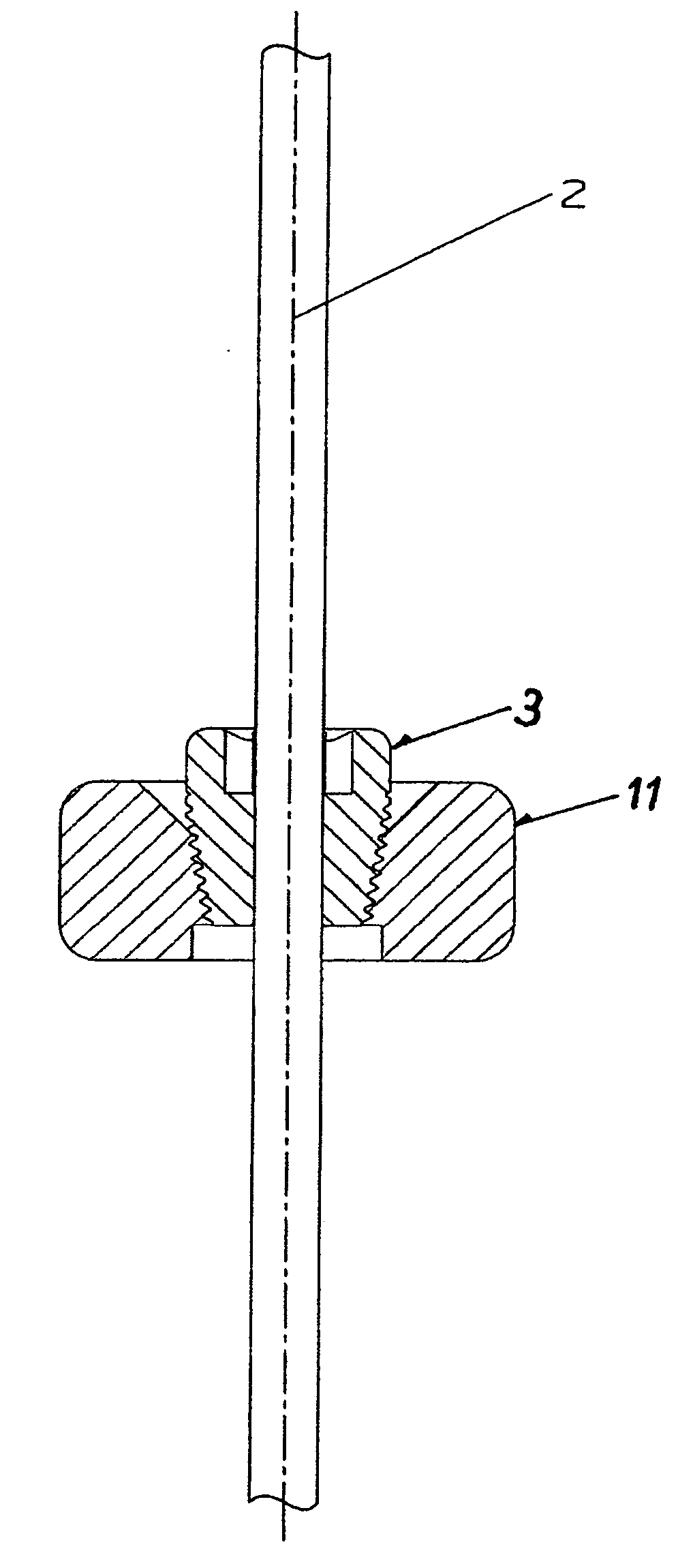
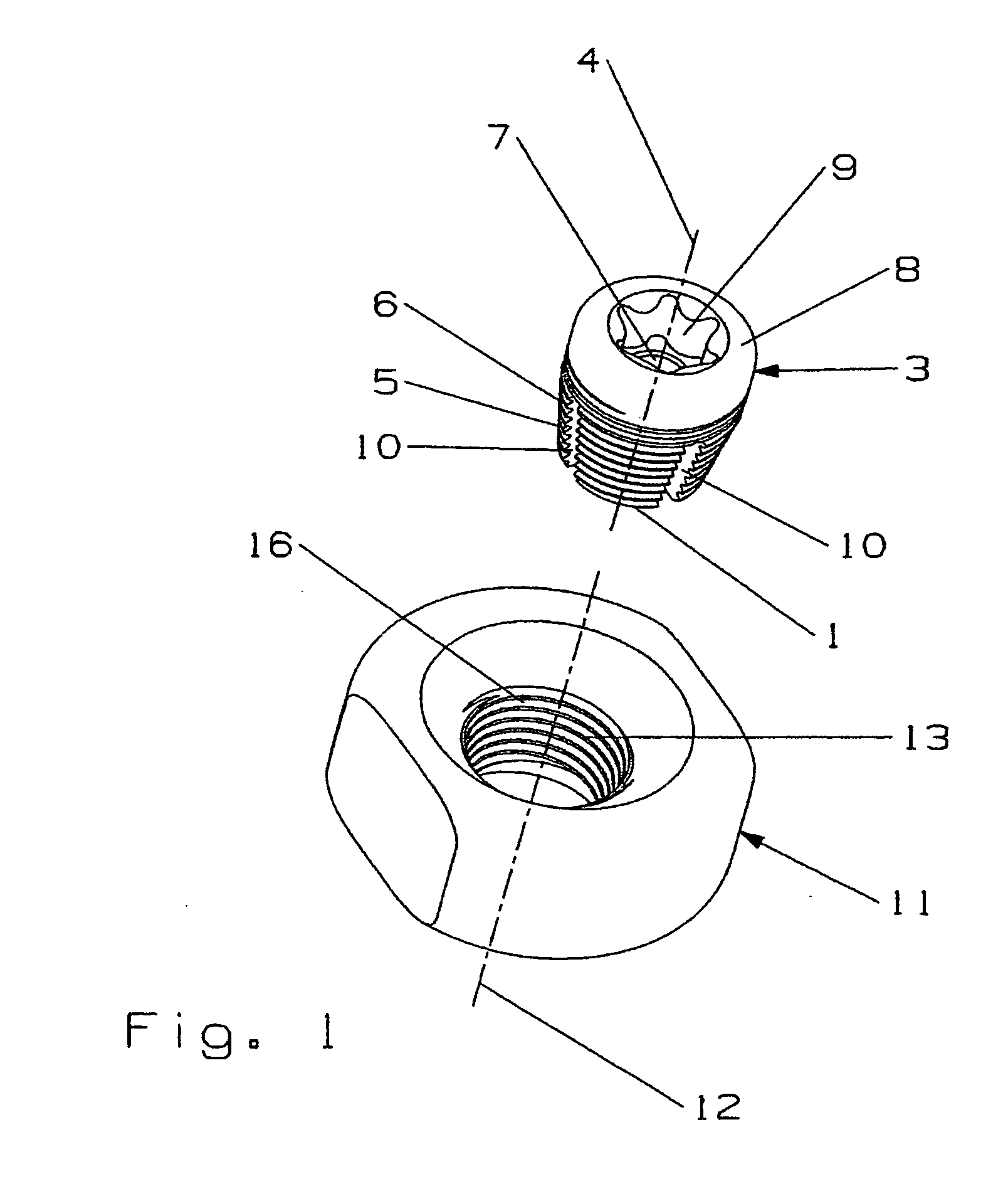
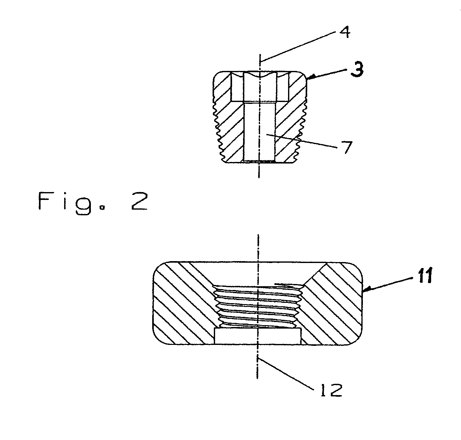
[0016] As illustrated in FIGS. 1 and 2, the clamping device may include a body or screw 3 and a receiving member (e.g., clamping ring 11). The screw 3 may have a partly truncated conical shape and may have a through bore 7. It should, however, be understood that those of ordinary skill in the art will recognize many modifications and substitutions which may be made to various elements of the present invention. The clamping device of the present invention may be used for paediatric application, but may also be used in adults at well. The clamping device may be used to connect a fixation element to any bone in the body (e.g., proximal end of the humerus).

[0017] The screw 3 may have a front end 1, a rear end 8, an outer surface, an inner surface and a height from the front end 1 to the rear end 8 of between about 3 mm and about 7 mm. Moreover, the outer surface of the screw 3 may taper from a rear end 8 to a front end 1 such that the taper is between about 15° and about 25° and such t...


PUM


Abstract

A device for clamping a fixation element which may allow for repositioning of the fixation element. The device may include a body comprising a front end, a rear end, an outer surface, a through bore extending between the front end and the rear end, a structure enabling deformation of at least a portion of the body, and a thread along at least a portion of the outer surface. The body may be tapered and the through bore may be sized and configured to receive a fixation element. The clamping device may also comprise a receiving member having a tapered bore with an inner thread sized and configured to receive the thread of the body. Insertion of the body into the tapered bore of the receiving member may result in at least a portion of the body being deformed. As the body is inserted into the tapered bore, the dimension of the through bore may decrease so that the body firmly engages the fixation element. Such a construction may allow for the body to be loosened from the tapered bore, the fixation element, body or receiving member to be repositioned, and the body re-tightened into the tapered bore.

Description

CROSS REFERENCE TO RELATED APPLICATION [0001] The present application is a continuation of International Patent Application PCT / CH2003 / 000538 filed Aug. 8, 2003, the entire content of which is expressly incorporated herein by reference thereto.FIELD OF THE INVENTION [0002] The invention relates to a device for holding a fixation element and, in particular, a device which enables the fixation element to be repositioned. BACKGROUND OF THE INVENTION [0003] In paediatrics, it is desirable to treat fractures of bone in the vicinity of a growth joint while, at the same time, avoiding injury to the growth joint. If the growth joint is injured, the bone will not continue to grow. Therefore, instead of bone screws which are usually used in osteosynthesis, Kirschner wires are used for treating fractures. Kirschner wires have a small diameter and, thus, use of Kirschner wires result in only marginal damage to the growth joint and possibly no injury to the growth joint. The disadvantage of usin...

Claims


Application Information

Patent Timeline
IPC IPC(8): A61B17/58A61B17/60A61B17/80A61B17/86F16B2/06F16B9/02
CPCA61B17/60A61B17/8047A61B17/863A61B17/864A61B2017/8675F16B2/065F16B9/026F16B9/056F16B9/054A61B17/84A61B17/68A61B17/58A61B17/56
Inventor SCHLAFLI, CHRISTOPHGICQUEL, PHILIPPENIEDERBERGER, ALFRED
Owner SYNTHES USA
Features
  • Generate Ideas
  • Intellectual Property
  • Life Sciences
  • Materials
  • Tech Scout
  • Unparalleled Data Quality
  • Higher Quality Content
  • 60% Fewer Hallucinations
Learn More