

Lens array and display apparatus using same
- Summary
- Abstract
- Description
- Claims
- Application Information
AI Technical Summary
Benefits of technology
Problems solved by technology
Method used
Image

Examples
first embodiment
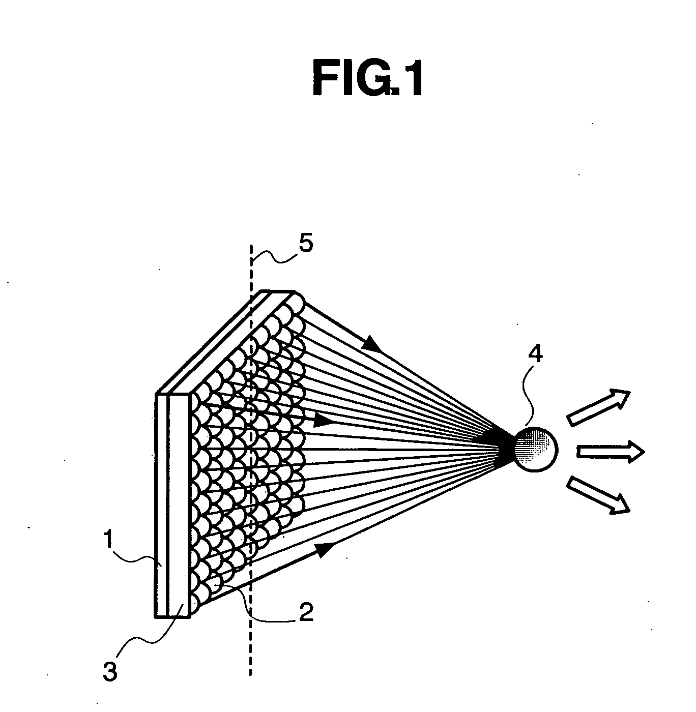
[0031]FIG. 13 is a view of a basic configuration of the present invention. An autostereoscopic display using an integral photography method is configured of a lens array 3 and an image processing device 1. In the case that the image display device 1 is an LC (liquid crystal) display, the device is configured of an LC panel, a back light panel, and driving device. Alternatively, in the case that the image display device 1 is self-emitting display, such as an organic EL display, the device is configured of an organic EL panel and a driving device. The lens array 3 is not limited to exist on the front surface of the image processing device 1, but a color filter or the like may exist between the lens array 3 and the image display device 1. Alternatively, depending on the solid phase of the image display device 1, the lens array 3 may be included in the interior of the image display device 1.
[0032] A lens array is a light beam control device that controls light beams emitted from an ima...
second embodiment
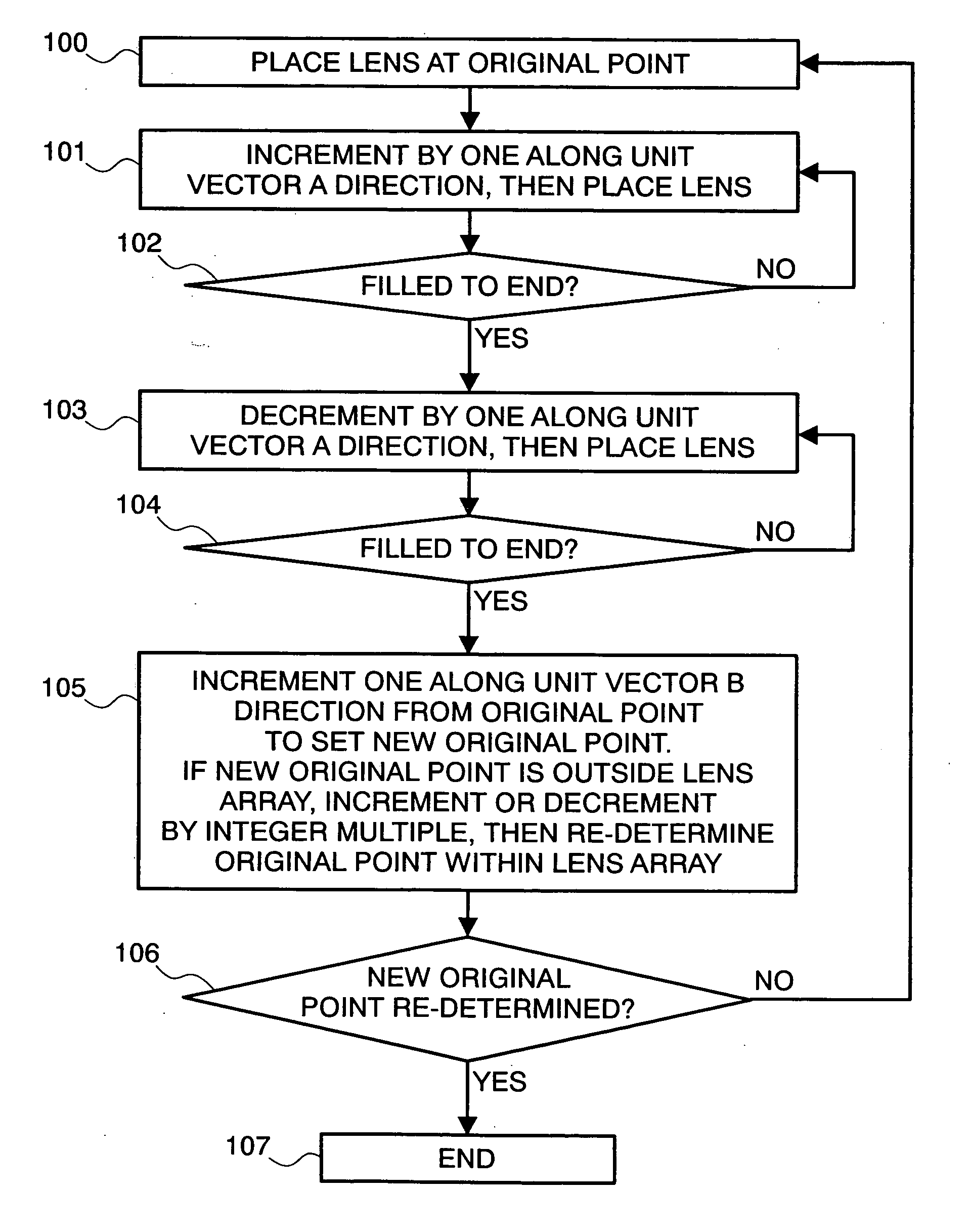
[0071]FIG. 11 is a view showing a lens arrangement. More specifically, FIG. 11 is an enlarged view of a part of a lens array 3 as viewed in the direction of the normal of the lens array surface. A matrix element 11 represents the unit length, and one matrix element 11 corresponds to one pixel of an image processing device 1. Two unit vectors are respectively represented by unit vectors A and B, the unit vector A having a horizontal length of 6 and a vertical length of 1, and unit vector B having a horizontal length of 1 and a vertical length of 3. The center of the respective lens 2 (lens center) is arranged in a position represented by an integer coefficient linear combination. The lens center indicates an optical axis center of the lens; and more specifically, it coincides with the center of the circle in the case of a simple spherical lens, but does not all time coincides with the lens center in the case of an aspherical lens. Even for a simple spherical lens, the lens center may...
third embodiment
[0073]FIG. 12 is a view showing a lens arrangement. More specifically, FIG. 12 is an enlarged view of a part of a lens array 3 as viewed in the direction of the normal of the lens array surface. A matrix element 11 represents the unit length, and one matrix element 11 corresponds to one pixel of an image processing device 1. Two unit vectors are respectively represented by unit vectors A and B, the unit vector A having a horizontal length of 4 and a vertical length of 3, and unit vector B having a horizontal length of −1 and a vertical length of 5. The center of the respective lens 2 (lens center) is arranged in a position represented by an integer coefficient linear combination. The lens center indicates an optical axis center of the lens; and more specifically, it coincides with the center of the circle in the case of a simple spherical lens, but does not all time coincides with the lens center in the case of an aspherical lens. Even for a short spherical lens, the lens center may...
PUM
 Abstract
Description
Claims
Application Information