Arthroscopic shaver with two pass inner blade and method of manufacturing same

a technology of shaver blade and inner blade, which is applied in the field of shaver blade for arthroscopic surgery, can solve the problems of inability to retain enough “bite” of the inner cutting edge, inability to efficiently cut tissue, and undesirable tearing, etc., and achieves the effect of high resection efficiency

Inactive Publication Date: 2006-09-07
ARTHREX
View PDF10 Cites 42 Cited by
  • Summary
  • Abstract
  • Description
  • Claims
  • Application Information

AI Technical Summary

Benefits of technology

[0017] Accordingly, it is an object of the present invention to produce an arthroscopic sha

Problems solved by technology

That is, because the tissue is already preferentially oriented in the direction of the rotation of the approaching inner cutting edge, it is difficult for that inner cutting edge to have sufficient “bite” to retain the tissue in the cutting window for resection.
The regions of the edges formed between the teeth have large included angles which are inefficient for cutting tissue.
Such tearing is undesirable since the torn tissue may frequently become wrapped into the gap between the inner and outer tubes and cause clogging.
While advanced tooth geometries such as those described in U.S. Pat. No. 6,053,928 to Van Wyk et al. have been produced for outer cutting edges with teeth, corresponding improvements have not been made in the geometry of the inner cutting edges with teeth.
However, this two-step approach to making teeth has drawbacks.
EDM is used to remove the ma

Method used


Image

  • Arthroscopic shaver with two pass inner blade and method of manufacturing same
  • Arthroscopic shaver with two pass inner blade and method of manufacturing same
  • Arthroscopic shaver with two pass inner blade and method of manufacturing same

Examples


Embodiment Construction

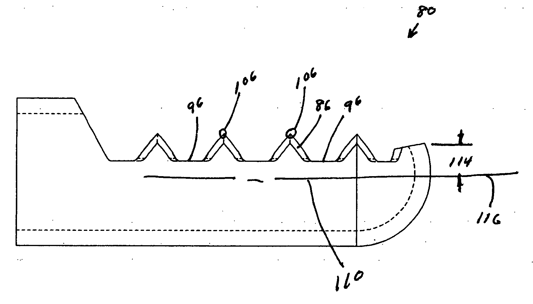
[0077]FIGS. 14 and 15 show the distal end of a shaver 79 formed in accordance with the principles of the present invention and having an inner tube 80 and an outer tube 81.

[0078] The distal end of an improved shaver inner tube with cutting edges formed in accordance with the principles of the present invention is shown in FIGS. 16 through 19. Shaver inner tube 80 has an inner lumen 82, and a cutting window 83 forming a first lateral cutting edge 84 having a plurality of teeth 86 spaced apart by distance 88. Shaver inner tube 80 also has a second lateral cutting edge 90 having a plurality of teeth 92 spaced apart by distance 94, distances 88 and 94 being equal. Teeth 86 are separated by flats 96 and teeth 92 are separated by flats 98. Teeth 86 and teeth 92 do not have a constant cross-section (FIG. 17), but rather decrease in width as they approach the inner lumen of the tube when viewed in a plan view (FIG. 16). Similarly, crests 100 of teeth 86 and crests 102 of teeth 92 are not p...


PUM

PropertyMeasurementUnit
Angleaaaaaaaaaa
Angleaaaaaaaaaa
Angleaaaaaaaaaa

Abstract

An arthroscopic shaver with an inner cutting window having a plurality of teeth positioned along the lateral cutting edges, the teeth being configured for easy penetration into tissue to prevent ejection of tissue from the cutting window during closure. The inner cutting edges are formed complete by a predetermined sequence of positioning moves and grinding passes on a multi-axis grinding machine. The teeth may be symmetrically or asymmetrically placed about the tube axis when viewed in a plan view.

Description

[0001] The present application claims the benefit of U.S. Provisional Application Ser. No. 60 / 657,420, filed on Mar. 2, 2005, the disclosure of which is incorporated by reference herein.FIELD OF THE INVENTION [0002] The present invention relates to arthroscopic surgery and, more particularly, to a shaver blade for arthroscopic surgery. BACKGROUND OF THE INVENTION [0003] Resection of tissue by an arthroscopic shaver blade is accomplished by cooperative interaction between the edges of the inner and outer cutting windows. As the inner and outer windows come into alignment, tissue is sucked into the opening formed by these windows. Continued rotation of the inner member causes the inner cutting edges to approach the outer cutting edges. Tissue in the cutting window between the inner and outer edges is either trapped between the edges or ejected from the window. Tissue trapped between the edges is either cut by the edges as they approach each other, or torn by the cutting edges as they ...

Claims


Application Information

Patent Timeline
IPC IPC(8): B23P13/04
CPCA61B17/32002A61B2017/00526Y10T29/49995B24B19/02B24B3/60
Inventor VAN WYK, ROBERT A.
Owner ARTHREX
Why Eureka
Try Eureka