Embedded abrasive cloth reel type sanding machine

A technology of sanding machine and emery cloth, applied in the field of sanding machine, can solve the problems of inability to guarantee the synchronous movement of both ends of the drum, failure to achieve sanding treatment effect, inconvenient operation, etc., so as to improve cutting efficiency and save replacement time. , the effect of improving efficiency

Active Publication Date: 2018-12-18
宁国市吉思知识产权运营有限公司
View PDF5 Cites 3 Cited by
  • Summary
  • Abstract
  • Description
  • Claims
  • Application Information

AI Technical Summary

Problems solved by technology

[0003] As the name suggests, sanding machine is the mechanical equipment used to complete the sanding work. It involves a wide range of industries and has a variety of categories. Traditional sanding machines usually use conveyor belts to drive the rollers to move, and then use motors to drive the rollers to run, so as to clean the surface of the workpiece in contact with it. Carry out sanding treatment, but the general sanding machine adopts to adjust the height of the drum to meet the different sizes of the workpiece. This structure has the following disadvantages: Since the drum parts must meet the requirements of horizontal movement and rotation, the height adjustment is added on this basis. The structure increases the complexity of the roller bracket, and it is troublesome to adjust the roller according to the workpiece, and it is inconvenient to operate, especially for some precision adjustments, it needs to be corrected repeatedly, which is very troublesome; for the surface finishing of the workpiece, the traditional belt drive method , there will be shaking and slipping during the moving process of the roller, and it is impossible to ensure that the two ends of the roller move synchronously, and the ideal sanding effect cannot be achieved.

Method used


Image

  • Embedded abrasive cloth reel type sanding machine
  • Embedded abrasive cloth reel type sanding machine
  • Embedded abrasive cloth reel type sanding machine

Examples


Embodiment 1

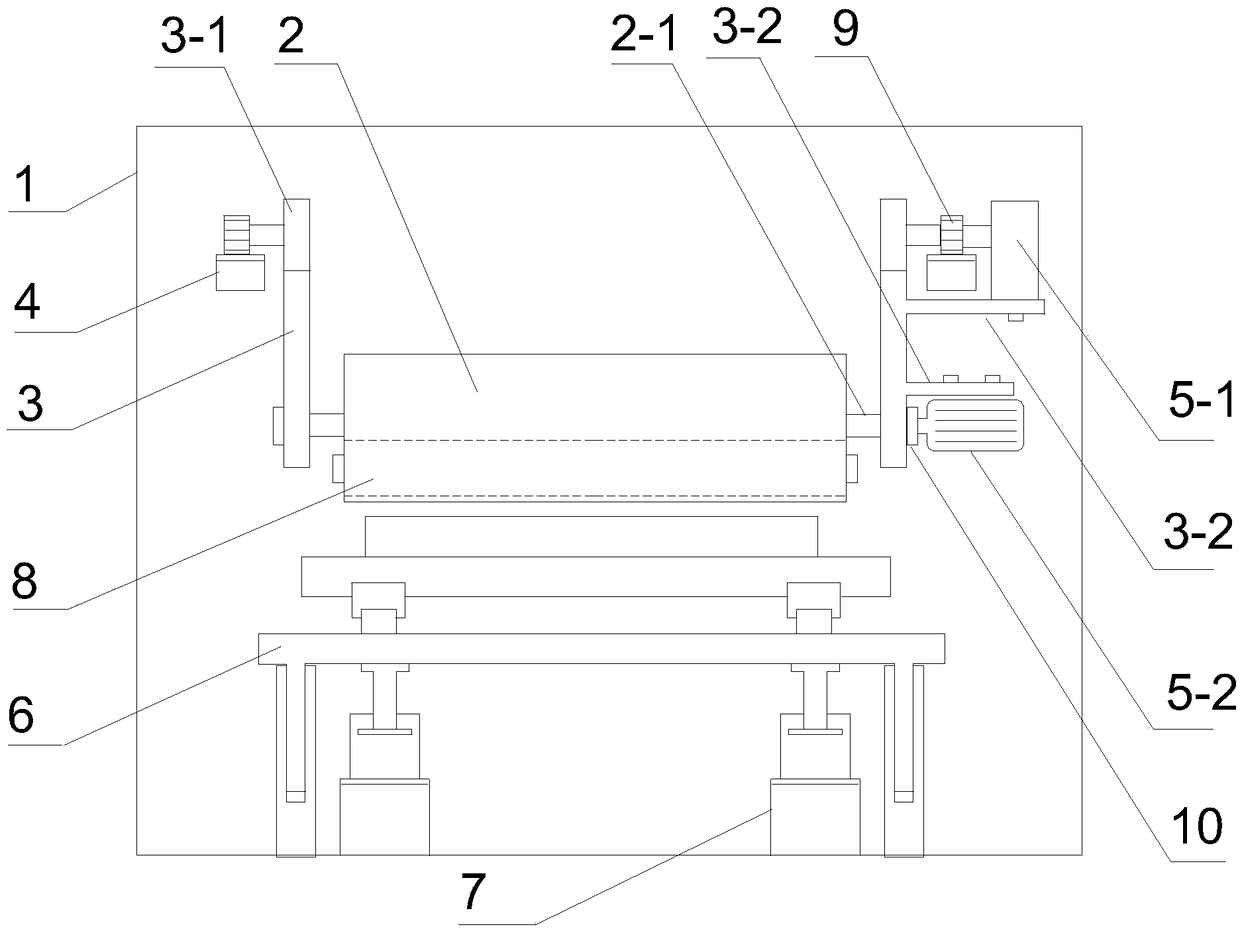
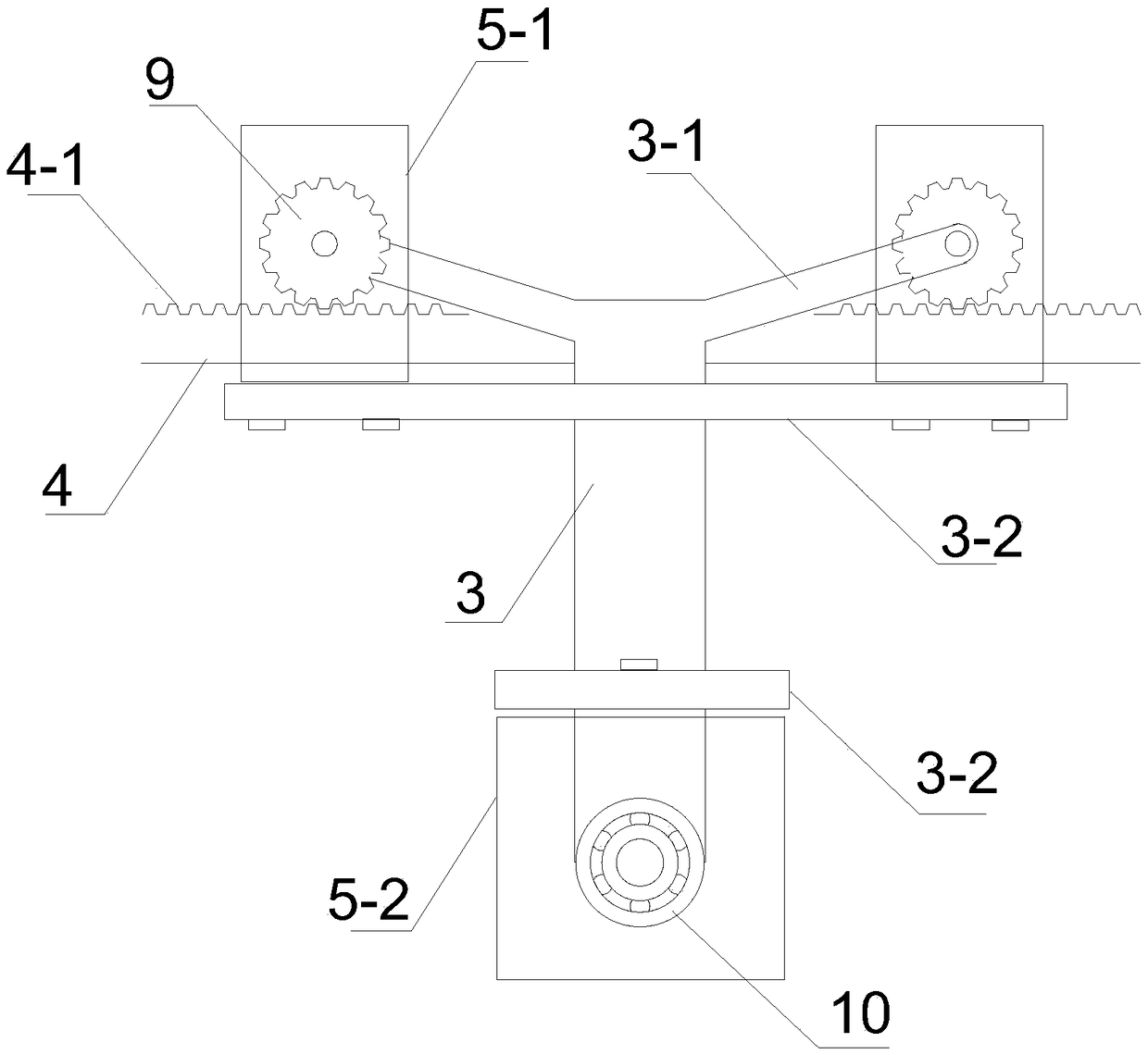
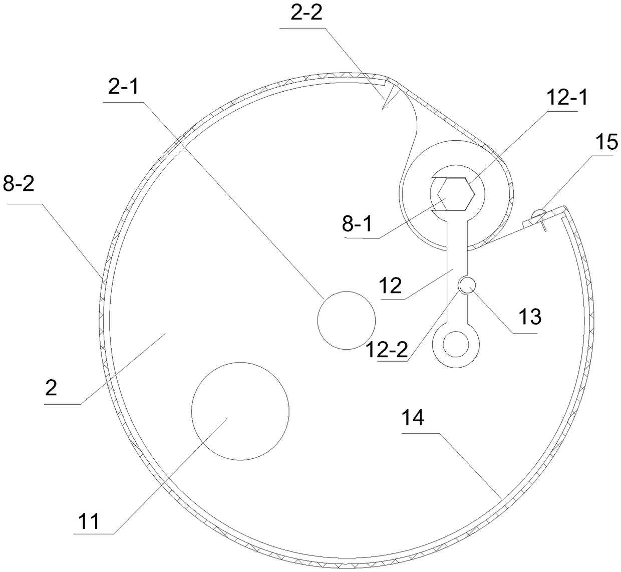
[0026] A drum type sander with embedded emery cloth, comprising a box body 1, and also includes a main drum 2, a boom 3, a beam frame 4, a driving motor 5, a processing platform 6 and a four-column support structure 7 arranged in the box body, the The main drum 2 is embedded with a gauze reel 8, and the two ends of the main drum 2 are provided with a shaft body 2-1, and the top of the boom 3 is connected with a support arm 3-1 which is inclined upward to both sides, The end of the support arm 3-1 extends laterally outwards and is connected with a gear 9. The beam frame 4 is erected inside the box body 1, and the beam frame 4 is provided with a rack 4-1 meshing with the gear 9. , the bottom of the boom 3 is provided with a ball bearing 10, the boom 3 is also provided with a side mounting plate 3-2, and the driving motor 5 is connected to the side mounting plate 3-2, wherein the first driving motor 5 -1 drives the gear to rotate, the output shaft of the second driving motor 5-2 ...


PUM


Abstract

The invention relates to a sanding machine, in particular to an embedded abrasive cloth reel type sanding machine which mainly solves the problem that an existing sanding machine is unreasonable in structure. The sanding machine further comprises a main roller, a lifting arm, a beam frame, drive motors, a processing platform and a four-column supporting structure which are arranged in a box body,wherein an abrasive cloth reel is embedded into the main roller; the two ends of the main roller are equipped with shaft bodies; the top of the lifting arm is connected with supporting arms, two endsof each supporting arm are arranged upwards in an inclined mode; the end parts of the supporting arms transversely extend outwards, and are connected with gears; the beam frame is arranged inside thebox body; racks which are engaged with the gears are arranged on the beam frame; rolling ball bearings are arranged in the bottom of the lifting arm; side mounting plates are further arranged on the lifting arm; and the drive motors are connected with the side mounting plates. Compared with a conventional sanding machine roller which adopts belt transmission to drive horizontal movement, the scheme adopts a structure of combining the gears with the racks, has limiting effect in rotation, and realizes synchronous movement, no shake and no off-tracking of the main roller.

Description

technical field [0001] The invention relates to a sanding machine, in particular to a drum type sanding machine embedded with abrasive cloth. Background technique [0002] Sanding and grinding are synonymous words, which refer to the physical removal of some materials and objects that are uneven, uneven in thickness, and do not meet the process requirements through abrasive cloth, grinding wheel, sandpaper, scouring pad, non-woven polishing wheel, etc., so that It is more smooth and flat, uniform in thickness, and a method to make it up to standard by technology. It is used in various veneer production, standard structural parts production, toy handicraft industry, decoration and furniture industry, floor wall panel building materials industry and so on. [0003] As the name suggests, sanding machine is the mechanical equipment used to complete the sanding work. It involves a wide range of industries and has a variety of categories. Traditional sanding machines usually use c...

Claims


Application Information

Patent Timeline
Patent Type & Authority Applications(China)
IPC IPC(8): B24B55/00B24B41/06B24B47/12B24B41/04B24B27/00
CPCB24B27/00B24B41/04B24B41/06B24B47/12B24B55/00
Inventor 覃德华
Owner 宁国市吉思知识产权运营有限公司
Why Eureka
Try Eureka