Turnip crop root removing device

A technology for crops and radishes, which is applied in the field of rhizome removal devices for radish crops, which can solve the problems of danger and trouble, low work efficiency, and increased processing costs, and achieve the effect of speeding up the cleaning process and improving the cutting efficiency

Inactive Publication Date: 2018-11-23
贵州伊诺生物科技有限公司
9 Cites 3 Cited by

AI-Extracted Technical Summary

Problems solved by technology

Before the radish crops are sold, the stems and leaves need to be removed. The current method of removing the stems and leaves of radish crops is that workers use scissors or knives to cut t...

Method used

The present invention is easy to use, and cylinder 30 drives two scissors blades 35 to close or separate, and then can excise the stem and leaf of radish crops, clip 4 can clamp the stem and leaves of radish crops, and by hanging conveying line 1 work, can The radish crops are continuously fed into the cutting mechanism 20 to improve the root cutting efficiency of the radish crops. The cleaning mechanism 10 can remove the soil on the surface of the radish crops rhizomes. In addition, the gas enters the cleaning box 16 through the air intake mechanism 13, which can make the The roots of radish crops are in a tumbling state, which speeds up the cleaning process and realizes the integrated operation of cutting and cleaning. It is suitable for assembly line processing and saves time and effort.
When in use: connect the external power supply, start the control switch group 7, clamp the cauline leaves of the radish crops with clip 4, start the suspension conveyor line 1, the suspension conveyor line 1 drives the radish crops to move, an...

Abstract

The invention discloses a turnip crop root removing device. The device comprises a base, a control switch group is arranged on one side of the upper surface of the base, a support plate is arranged atone end of the left side of the upper surface of the base, a removing mechanism is arranged at the upper end of the support plate, a hanging conveyor line is located over the removing mechanism, hanging mechanisms are uniformly distributed on the hanging conveyor line, four support legs are arranged on the left side of the upper surface of the base, a collecting box is arranged at the upper endsof the four supporting legs and located under the removing mechanism, a sliding plate is connected to the right side face of the collecting box, a cleaning box is arranged on the right side of the upper surface of the base, a cleaning mechanism is arranged in the middle in the cleaning box, and an air inlet mechanism is arranged on the lower portion of the right side face of the cleaning box. Theturnip crop root removing device is convenient to use, the turnip crop root removing efficiency is improved, turnip crop roots can be cleaned conveniently, removing and cleaning integrated operation is achieved, the device is suitable for assembly line processing, and time and labor are saved.

Application Domain

Food treatment

Technology Topic

EngineeringAssembly line +4

Image

  • Turnip crop root removing device
  • Turnip crop root removing device
  • Turnip crop root removing device

Examples

  • Experimental program(1)

Example Embodiment

[0022] The following will clearly and completely describe the technical solutions in the embodiments of the present invention with reference to the accompanying drawings in the embodiments of the present invention. Obviously, the described embodiments are only some, not all, embodiments of the present invention. Based on the embodiments of the present invention, all other embodiments obtained by persons of ordinary skill in the art without making creative efforts belong to the protection scope of the present invention.
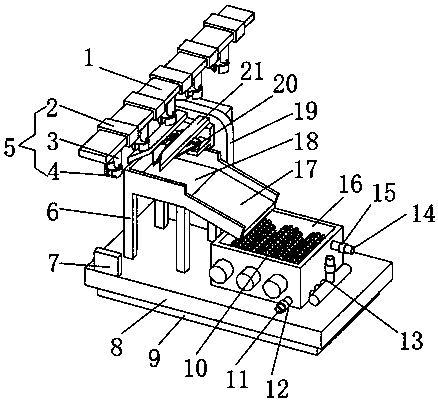
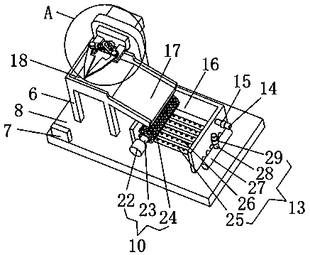
[0023] see Figure 1-3 , the present invention provides a technical solution: a radish crop rhizome cutting device, including a base 8, the lower surface of the base 8 is provided with a frame 9, the frame 9 is a rectangular frame, and one side of the upper surface of the base 8 is provided with a control switch group 7. The input end of the control switch group 7 is electrically connected to the output end of the external power supply, which is convenient for manipulation. The left end of the upper surface of the base 8 is provided with a support plate 19, and the upper end of the support plate 19 is provided with a cutting mechanism 20. The support plate 19 The side surface is provided with a guide mechanism, the guide mechanism is located directly above the cutting mechanism 20, the guide mechanism includes a guide plate 21, the number of the guide plate 21 is two, and the opening ends of the two guide plates 21 are arc-shaped, which is convenient for the removal of radish crops. The rhizomes enter the cutting mechanism 20, the cutting mechanism 20 includes a cylinder 30, the cylinder 30 is connected with an external air source, the two ends of the side surface of the cylinder 30 are provided with connecting arms 32, and the ends of the connecting arms 32 are hinged with movable arms 34, One end of movable arm 34 is provided with scissors blade 35, and the middle part of movable arm 34 is provided with through groove 33, and movable rod 31 is movably socketed in two through grooves 33, and movable rod 31 is connected with the telescoping end of cylinder 30, through external air The source drives the cylinder 30, and the cylinder 30 pushes the movable rod 31 to move, and the movable rod 31 moves in the two through slots 33, which can drive the two movable arms 34 to separate or close, and then can drive the two scissor blades 35 to close or separate, and cut the radish Stems and leaves of similar crops, the upper left side of the base 8 is provided with a suspension conveying line 1, and the suspension conveying line 1 is located directly above the cutting mechanism 20, and the input end of the suspension conveying line 1 is electrically connected with the output end of the control switch group 7, Suspension mechanism 5 is evenly distributed on the suspension conveying line 1, suspension mechanism 5 includes connecting seat 2, the lower surface of connecting seat 2 is provided with elastic rope 3, and the lower end of elastic rope 3 is provided with clip 4, and clip 4 is convenient to clamp radish crops The stems and leaves of the radish crops can be sent to the cutting mechanism 20 through the suspension conveying line 1, and the stems and leaves are separated from the rhizomes through the work of the cutting mechanism 20, so that the radish crops can be continuously transported, and the cutting efficiency of the rhizomes can be improved. The base 8 The left side of the upper surface is provided with support legs 6, the number of support legs 6 is four, and the upper ends of the four support legs 6 are provided with collection boxes 18 for collecting rhizomes, the collection box 18 is located directly below the cutting mechanism 20, and the collection box The right side of 18 is connected with slide plate 17, and the upper surface right side of base 8 is provided with cleaning box 16, and rhizome slides into cleaning box 16 by slide plate 17, and the front side bottom of cleaning box 16 is provided with blowdown pipe 11, and blowdown pipe 11 The middle part is provided with a sewage valve 12, which is convenient for sewage discharge. The upper right side of the cleaning tank 16 is provided with a water inlet pipe 14, and the middle part of the water inlet pipe 14 is provided with a water inlet valve 15, which is convenient for adding water. Mechanism 10, the quantity of cleaning mechanism 10 is three and equidistantly arranged, and cleaning mechanism 10 comprises rotating rod 23, and the outer surface of rotating rod 23 is sleeved with hair roller 24, and one end of rotating rod 23 runs through the front side of cleaning box 16 and Connect with the output shaft of the motor 22 through the shaft coupling, the input end of the motor 22 is electrically connected with the output end of the control switch group 7, and works through the motor 22 , the motor 22 drives the rotating rod 23 to rotate, and the rotating rod 23 drives the wool roller 24 to rotate, which can remove the soil on the surface of the radish crop rhizome. Trachea 28, the middle part of air intake pipe 28 is provided with intake valve 29, and the lower end of air intake pipe 28 is connected with main pipe 27, and the side surface of main pipe 27 is provided with branch pipe 26, and branch pipe 26 stretches into the inner bottom end of cleaning box 16, and branch pipe 26 The quantity is five and arranged at equal intervals, the outer surface of the branch pipe 26 is evenly distributed with small holes 25, the gas is sprayed out from the small holes 25 through the inlet pipe 28, the main pipe 27 and the branch pipe 26, and can evenly fill the inside of the cleaning box 16 Bottom, so that the roots of radish crops are in a rolling state, speed up the cleaning process, and realize the integrated operation of cutting and cleaning, which is suitable for assembly line processing and saves time and effort. There are buttons on the control switch group 7 to control the start and stop of the suspension conveyor line 1 and the motor 22 .
[0024] When in use: connect the external power supply, start the control switch group 7, clamp the stems and leaves of the radish crops with the clip 4, start the suspension conveyor line 1, the suspension conveyor line 1 drives the radish crops to move, and the radish crops pass through the guide plate 21 Entering the cutting mechanism 20, the external air source drives the cylinder 30 to work, the cylinder 30 pushes the movable rod 31 to move, and the movable rod 31 moves in the two through grooves 33, which can drive the two movable arms 34 to separate or close, and then can drive the two movable arms 34 to move. Two scissor blades 35 are closed or separated, and the stems and leaves of radish crops are cut off. The clips 4 clamp the stems and leaves and continue to move. The rhizomes fall into the collection box 18 and can work continuously. Start the motor 22, the motor 22 drives the rotating rod 23 to rotate, and the rotating rod 23 drives the hair roller 24 to rotate, which can remove the soil on the surface of the radish crop rhizome, open the air intake valve 29, and the gas passes through the air intake pipe 28, the main pipe 27 and the branch pipe 26 from The small holes 25 are sprayed out, which can make the roots of radish crops in a rolling state and speed up the cleaning process.
[0025]The present invention is easy to use, the cylinder 30 drives the two scissors 35 to close or separate, and then the stems and leaves of the radish crops can be cut off, the clip 4 can clamp the stems and leaves of the radish crops, and the radish can be cut by hanging the conveying line 1 to work. The crops are continuously sent into the cutting mechanism 20 to improve the cutting efficiency of the roots of the radish crops. The cleaning mechanism 10 can remove the soil on the surface of the roots of the radish crops. In addition, the gas enters the cleaning box 16 through the air intake mechanism 13, which can make the radish crops The rhizome is in a tumbling state, which speeds up the cleaning process and realizes the integrated operation of cutting and cleaning, which is suitable for assembly line processing and saves time and effort.
[0026] Although the embodiments of the present invention have been shown and described, those skilled in the art can understand that various changes, modifications and substitutions can be made to these embodiments without departing from the principle and spirit of the present invention. and modifications, the scope of the invention is defined by the appended claims and their equivalents.

PUM

no PUM

Description & Claims & Application Information

We can also present the details of the Description, Claims and Application information to help users get a comprehensive understanding of the technical details of the patent, such as background art, summary of invention, brief description of drawings, description of embodiments, and other original content. On the other hand, users can also determine the specific scope of protection of the technology through the list of claims; as well as understand the changes in the life cycle of the technology with the presentation of the patent timeline. Login to view more.

Similar technology patents

Transurethral bladder suturing system

InactiveCN112869796AImprove resection efficiencyResidue reduction
Owner:ZHONGSHAN HOSPITAL FUDAN UNIV

Immunomagnetic bead for sorting human cells and preparation and cutting-off method of immunomagnetic bead

ActiveCN105087788AImprove resection efficiency
Owner:SHANGHAI BAIZE MEDICAL APP & INSTR CO LTD +2

Adjustable spinal endoscopic intervertebral disc sawing cutting device

PendingCN113749721AIncreased scope of operationImprove resection efficiency
Owner:THE AFFILIATED HOSPITAL OF QINGDAO UNIV

Classification and recommendation of technical efficacy words

  • Improve resection efficiency

Immunomagnetic bead for sorting human cells and preparation and cutting-off method of immunomagnetic bead

ActiveCN105087788AImprove resection efficiency
Owner:SHANGHAI BAIZE MEDICAL APP & INSTR CO LTD +2

Adjustable spinal endoscopic intervertebral disc sawing cutting device

PendingCN113749721AIncreased scope of operationImprove resection efficiency
Owner:THE AFFILIATED HOSPITAL OF QINGDAO UNIV

Transurethral bladder suturing system

InactiveCN112869796AImprove resection efficiencyResidue reduction
Owner:ZHONGSHAN HOSPITAL FUDAN UNIV
Why Eureka
Try Eureka