
Managing device for an umbilical member of a robot and a robot having the managing device

Inactive Publication Date: 2006-09-07
FANUC LTD
View PDF11 Cites 15 Cited by
  • Summary
  • Abstract
  • Description
  • Claims
  • Application Information

AI Technical Summary

Benefits of technology

[0007] Therefore, an object of the present invention is to provide a managing device for an umbilical member having a simple structure, and a robot having the managing device, by which an interference region of the conduit is reduced as much as possible and an undesirable excess length of the conduit may be avoided without using the above spring, or the like.
[0010] The managing device may further comprise a means for reducing the sliding resistance between the forearm and the umbilical member.

Problems solved by technology

When the umbilical member is arranged around the wrist element of a robot arm, the umbilical member may contact the arm or the other external equipment and may be worn or damaged.
In the configuration disclosed in the above publication, as the holding means is positioned at generally a center of an upper surface of the forearm, it is difficult to closely fit the holding means to the forearm.
Therefore, there is a gap between the conduit and the forearm, resulting in that an interference area of the forearm may be enlarged.

Method used


Image

  • Managing device for an umbilical member of a robot and a robot having the managing device
  • Managing device for an umbilical member of a robot and a robot having the managing device
  • Managing device for an umbilical member of a robot and a robot having the managing device

Examples


Embodiment Construction

[0017] Embodiments of the invention will be described with reference to the drawings.

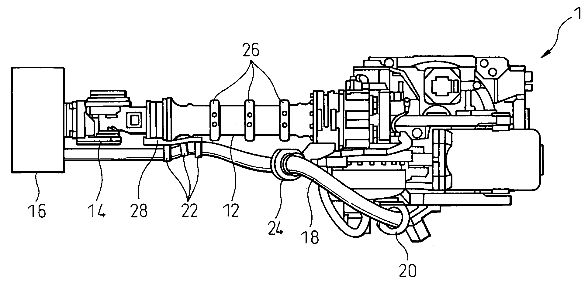
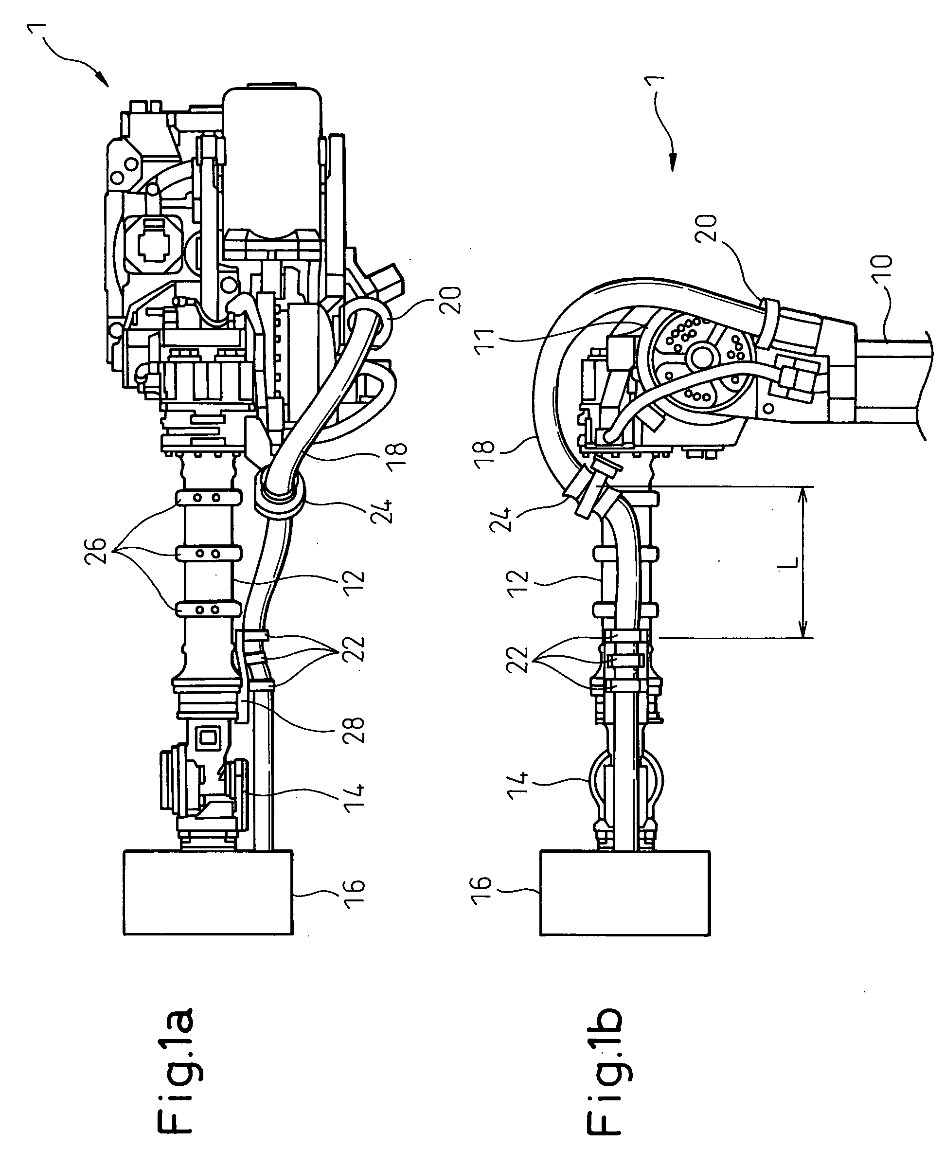
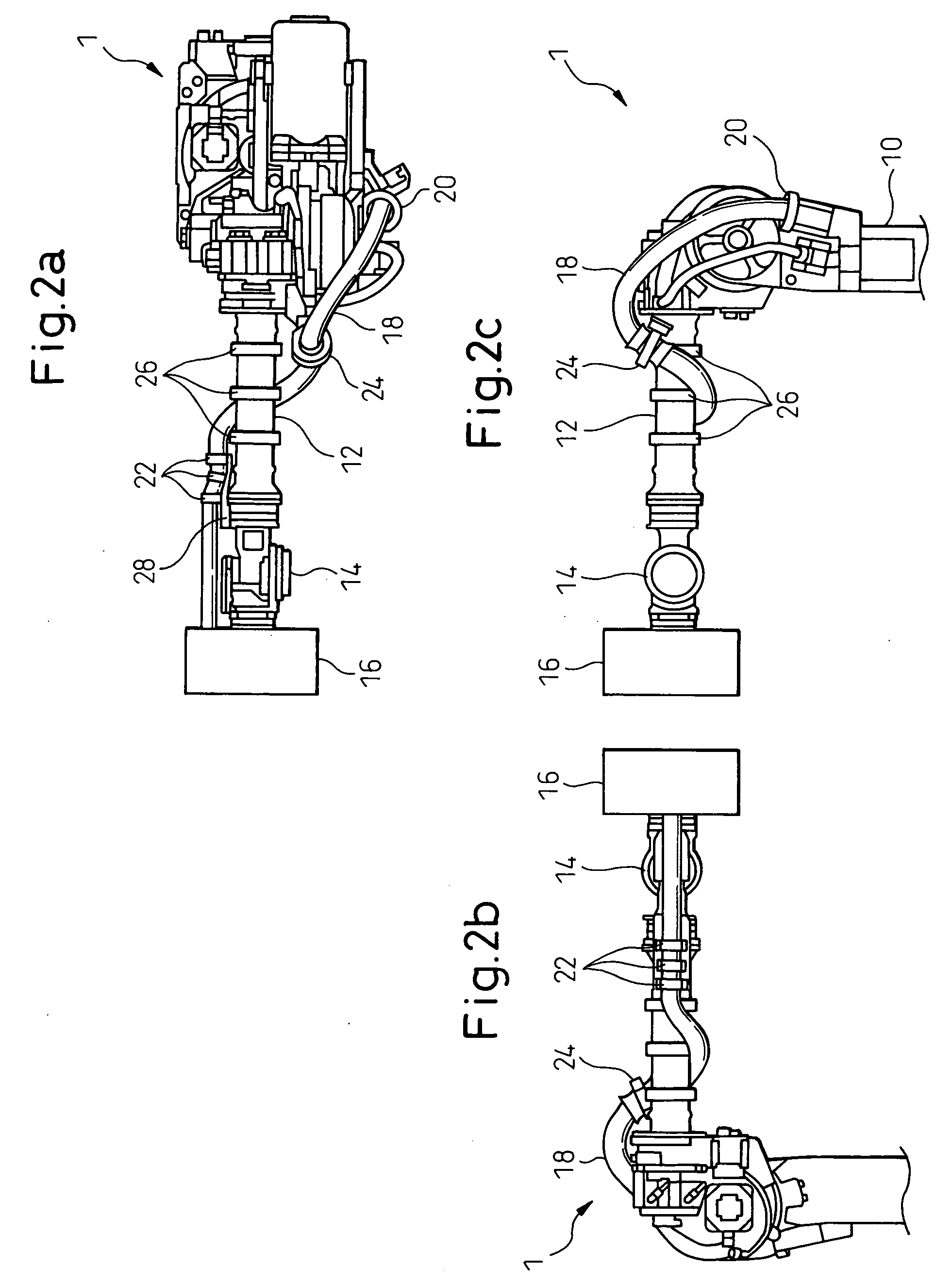
[0018]FIGS. 1a and 1b show a total configuration of a managing device of the invention, each showing a robot from an upper arm to an end effector. A robot 1 includes an upper arm 10; a forearm 12 movably connected to the upper arm 10 via a joint 11; a wrist element 14 rotatably mounted to the end of the forearm 12; and an end effector 16 attached to the wrist element 14. Power and a signal are sent to the end effector 16 by means of an umbilical member 18 constituted by a flexible conduit through which a cable and a tube extend. The umbilical member 18 is arranged along a base (not shown) of the robot 1, the upper arm 10, the forearm 12 and the wrist element 14 and connected to the end effector 16.

[0019] As shown in FIGS. 1a and 1b, a first supporting member or a conduit supporting member 20 is arranged on the upper arm 10, and a second supporting member or a conduit supporting member 22 is arrang...


PUM


Abstract

A managing device having a simple structure for an umbilical member or a conduit and a robot having the managing device, by which an interference region of the conduit is reduced as much as possible and the undesirable excess length of the conduit may be cancelled without using an auxiliary device. A first conduit supporting member is arranged on an upper arm of the robot and a second conduit supporting member is arranged on a wrist element of the robot. The conduit is fixed to or twistably supported by the first and second supporting member. Further, the conduit is held by a holding member, mounted between the first and second supporting member, in particular, adjacent to the side of a forearm of the robot, such that the conduit may slide relative to the holding member and may rotate about axes along and perpendicular to the sliding direction of the conduit. As the holding member is positioned as close to the forearm as possible, a gap between the conduit and the forearm is reduced and the possibility of interference between the conduit and an external equipment may be minimized.

Description

BACKGROUND ART [0001] 1. Technical Field [0002] The preset invention relates to a managing device, for an umbilical member including a cable and / or a tube of an industrial robot, and a robot having the managing device. [0003] 2. Description of the Related Art [0004] Generally, when an industrial robot is used for an operation, the robot is required to be provided with an umbilical member including a cable and / or a tube for transmitting power or a signal to an end effector attached to the end of a wrist element of the robot. When the umbilical member is arranged around the wrist element of a robot arm, the umbilical member may contact the arm or the other external equipment and may be worn or damaged. In order to avoid such an inconvenience, several configurations has been proposed. [0005] For example, Patent Publication No. EP1060057 discloses a configuration in which a flexible conduit, containing a cable and a tube, is arranged along a forearm of a robot, by means of a holding mea...

Claims


Application Information

Patent Timeline
IPC IPC(8): B25J18/00
CPCY10T74/20305B25J19/0025
Inventor KIDOOKA, AKIOMORIOKA, MASAHIRO
Owner FANUC LTD
Learn More