Pressure relief valve

Inactive Publication Date: 2006-09-07
CATERPILLAR INC
View PDF24 Cites 18 Cited by
  • Summary
  • Abstract
  • Description
  • Claims
  • Application Information

AI Technical Summary

Benefits of technology

[0010] In one aspect, the present disclosure is directed to a pressure relief valve that includes a valve body defining an inlet configured to receive fluid from a fluid system. The inlet defines a cross-sectional area. The valve body further includes a pressure control orifice ending in a valve seat. The pressure control orifice defines a cross-sectional area less than the cross-sectional area of the inlet. The valve body also includes a guideway extending from the valve seat. The pressure relief valve further includes a valve closing member configured to abut the valve seat in a closed position and to be displaced from the valve seat in an open position, thereby releasing pressure from the fluid system. The pressure relief valve also includes a flow member including a stem and a flow plate. The stem is operably associated with the valve closing member and is configured to reciprocate within the guideway. The pressure relief valve further includes a valve spring operably associated with the valve body. The valve spring is configured to exert a biasing force to hold the valve closing member via the flow plate against the valve seat in the closed position and to return the valve closing member to the closed position when the valve closing member is in the open position.
[0011] In another aspect, the present disclosure is directed to a fluid system that includes a pump configured to pressurize a fluid and a pressure relief valve configured to regulate pressure in the fluid system. The pressure relief valve includes a valve body defining an inlet configured to receive fluid from a fluid system. The inlet defines a cross-sectional area. The valve body further includes a pressure control orifice ending in a valve seat. The pressure control orifice defines a cross-sectional area less than the cross-sectional area of the inlet. The valve body also includes a guideway extending from the valve seat. The pressure relief valve further includes a valve closing member configured to abut the valve seat in a closed position and to be displaced from the valve seat in an open position, thereby rele

Problems solved by technology

Under certain circumstances, the pressure in the fuel system may reach a magnitude that could damage the components of the fuel system.
Such complex valve seat and valve closing member configurations, however, may be more expensive than desired.
This less complex and generally less expensive valve closing member, however, may be unsuitable due to its relatively unstable pressure relief characteristics.
In such an arrangement, however, once the pressure in the fluid system has been released by virtue of the ball-shaped valve closing member being unseated and displaced to release pressure, in order for the valve closing member to reseat and discontinue pressure relief, pressure in the fluid system may need to drop to an undesirably low magnitude because the fluid flowing through the aperture, once opened, prevents the ball-shaped valve closing member from reseating until the pressure drops signi

Method used


Image

  • Pressure relief valve
  • Pressure relief valve
  • Pressure relief valve

Examples


Embodiment Construction

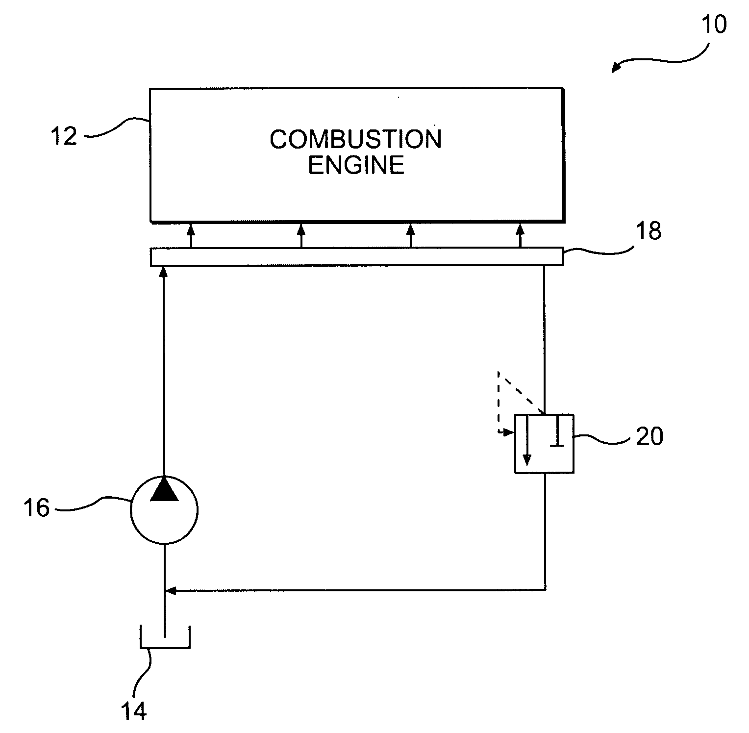
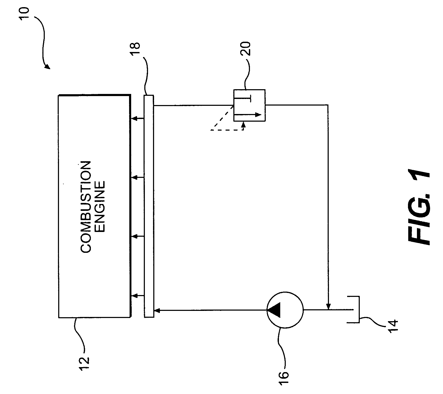
[0020]FIG. 1 illustrates an exemplary fluid system 10. Fluid system 10 is a fuel system for delivering fuel to a combustion engine 12, which may include a reservoir 14 for storing fuel, and a pump 16 for transferring fuel from reservoir 14 to combustion engine 12 via a manifold 18. Fuel system 10 may be configured to deliver fuel to combustion engine 12 under pressure, for example, ranging from about 300 bar to about 2,000 bar (e.g., from about 1,000 bar to about 2,000 bar (e.g., about 1,600 bar)). In order to prevent pressure in the fluid system 10 from reaching an undesirably high magnitude, fluid system 10 may be provided with a pressure relief valve 20, for example, a high pressure relief valve. Although fluid system 10 has been described for exemplary purposes in relation to a fuel system, principles contained in this disclosure may have application to other fluid systems known to those having skill in the art.

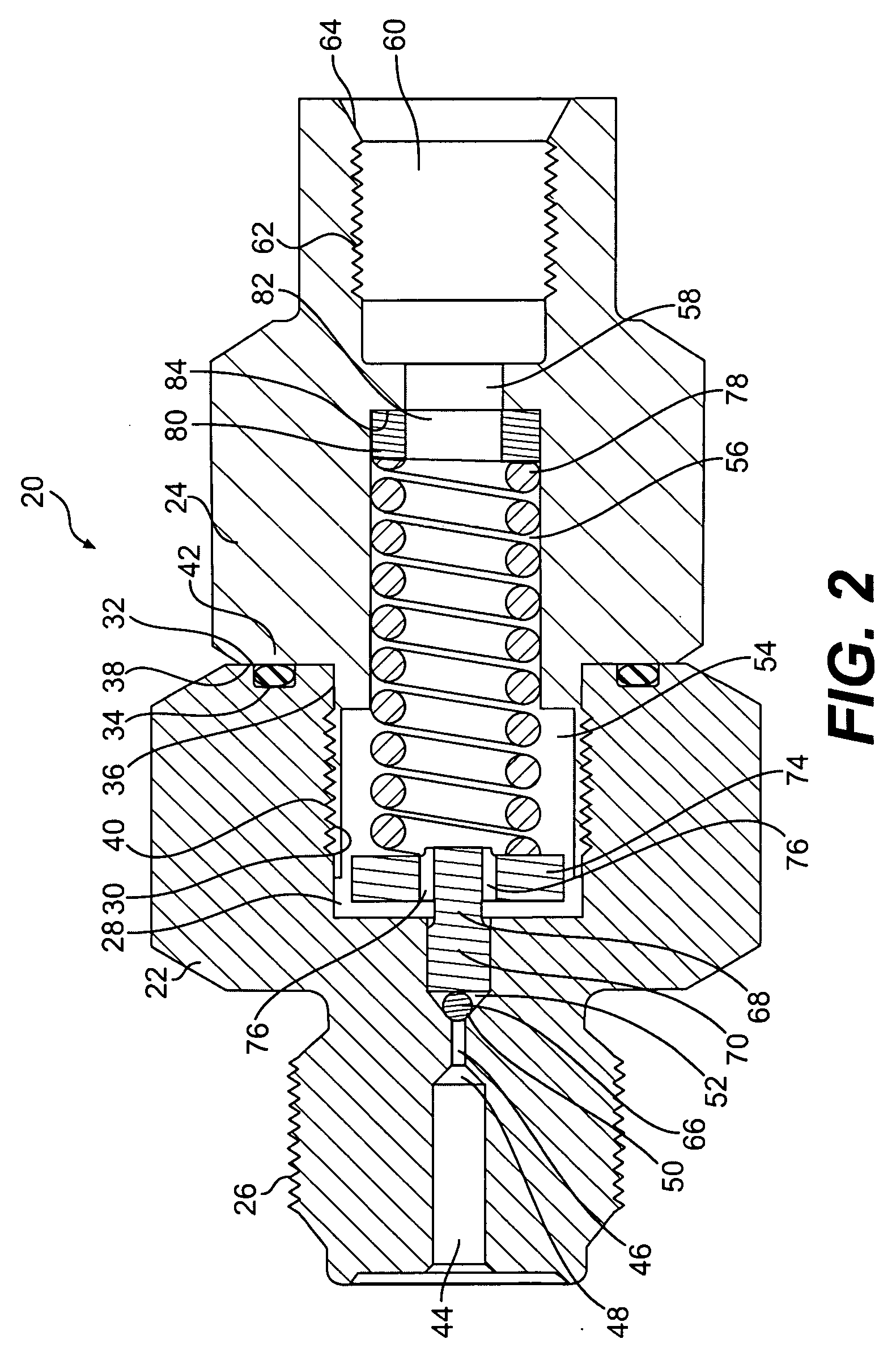
[0021]FIG. 2 illustrates an exemplary pressure relief valve 20, for...


PUM


Abstract

A pressure relief valve includes a valve body defining an inlet configured to receive fluid from a fluid system, a pressure control orifice ending in a valve seat, and a guideway extending from the valve seat. The pressure relief valve further includes a valve closing member configured to abut the valve seat in a closed position and to be displaced from the valve seat in an open position, thereby releasing pressure from the fluid system. The pressure relief valve also includes a flow member including a stem and a flow plate. The stem is operably associated with the valve closing member and is configured to reciprocate within the guideway. The pressure relief valve further includes a valve spring operably associated with the valve body.

Description

TECHNICAL FIELD [0001] The present disclosure relates generally to a pressure relief valve and, more particularly, to a pressure relief valve having a pressure control orifice. BACKGROUND [0002] In many fluid system applications, it may be desirable to relieve pressure in the fluid system, for example, in order to prevent damage to components of the fluid system and / or in order to prevent an abnormal condition. For example, a combustion engine may include a fuel system for supplying fuel to combustion chambers under pressure in order to provide appropriate atomization and mixing of combustion components. An example of one such fuel system is commonly referred to as a common rail fuel injection system. [0003] In a common rail fuel injection system, a pump, for example, a variable displacement pump, supplies fuel under high pressure, such as, for example, about 1,600 bar, to a manifold sometimes referred to as a common rail, which provides fuel to injectors associated with each of the...

Claims


Application Information

Patent Timeline
IPC IPC(8): F02M57/02G05D11/00F02M69/54
CPCF02M63/0012F02M63/005F02M63/0225F02M63/025F16K15/044F16K17/0406Y10T137/2582
Inventor STOCKNER, ALAN R.
Owner CATERPILLAR INC
Why Eureka
Try Eureka