Blow air control system

a control system and blow air technology, applied in the field of blow air control system, can solve the problems of low quality of parison, and product not having fine mold features, and achieve the effect of high quality

Inactive Publication Date: 2006-09-07
GRAHAM PACKAGING CO LP
View PDF7 Cites 6 Cited by
  • Summary
  • Abstract
  • Description
  • Claims
  • Application Information

AI Technical Summary

Benefits of technology

[0008] It is therefore an object of the present invention to provide novel blow air control systems for blow molding a container from a parison that allow blow molding equipment to be run at high speed without parison blow out, allow products having fine features of a mold and a high quality finish to be produced, and do not require expensive modification or replacement of molds.

Problems solved by technology

However, use of a high pressure to inflate the parison can lead to blow out during inflation.
It is thought that when blow out occurs, the lower differential of pressure within and outside of the parison can result in the parison exterior surface being pressed less firmly against the mold so that the product does not have fine features of the mold and has a poor quality finish.
When blow out occurs, the product may also have an opening in the region of the blow out, which can cause it to leak when filled with, for example, a gas, a liquid, or a finely divided solid.
It is thought that the higher temperature of the parison can result in the parison having lower strength so that blow out can occur with greater frequency than if blow molding equipment were run at a lower rate of output.
Developing and manufacturing molds which contain interstices through which low temperature fluid can flow to cool the parison would be expensive and lead to increased capital cost of blow molding equipment.
Furthermore, such a cooled mold may not be effective at cooling the parison before and while it is being inflated and before the exterior surface of the parison contacts the mold.
Developing and manufacturing new molds in which the mold dimensions are changed so that the mold is suitable for operation with blow molding equipment operating at a high production rate would be expensive.

Method used


Image

  • Blow air control system
  • Blow air control system

Examples


Embodiment Construction

[0015] Embodiments of the invention are discussed in detail below. In describing embodiments, specific terminology is employed for the sake of clarity. However, the invention is not intended to be limited to the specific terminology so selected. A person skilled in the relevant art will recognize that other equivalent parts can be employed and other methods developed without parting from the spirit and scope of the invention. All references cited herein are incorporated by reference as if each had been individually incorporated.

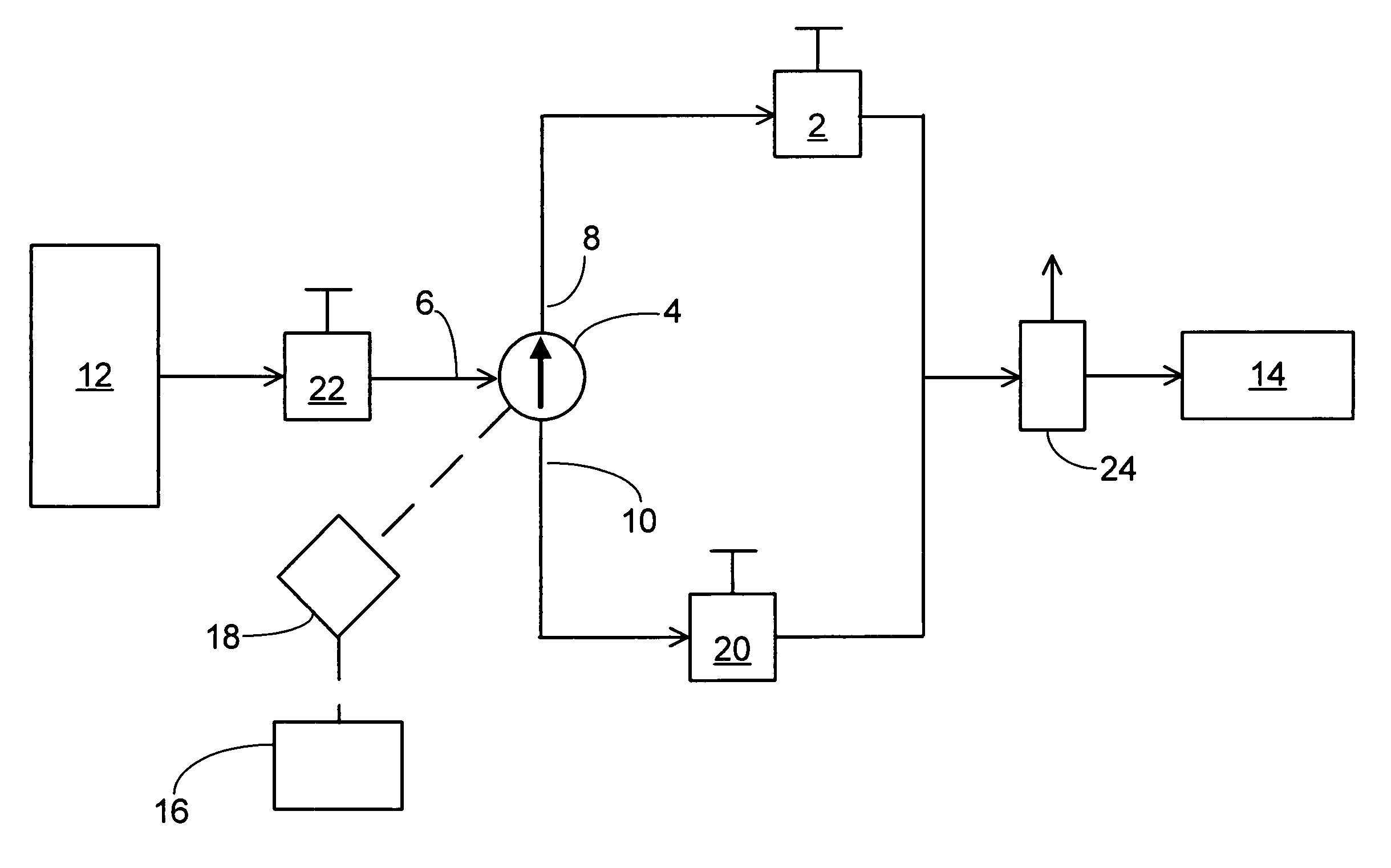
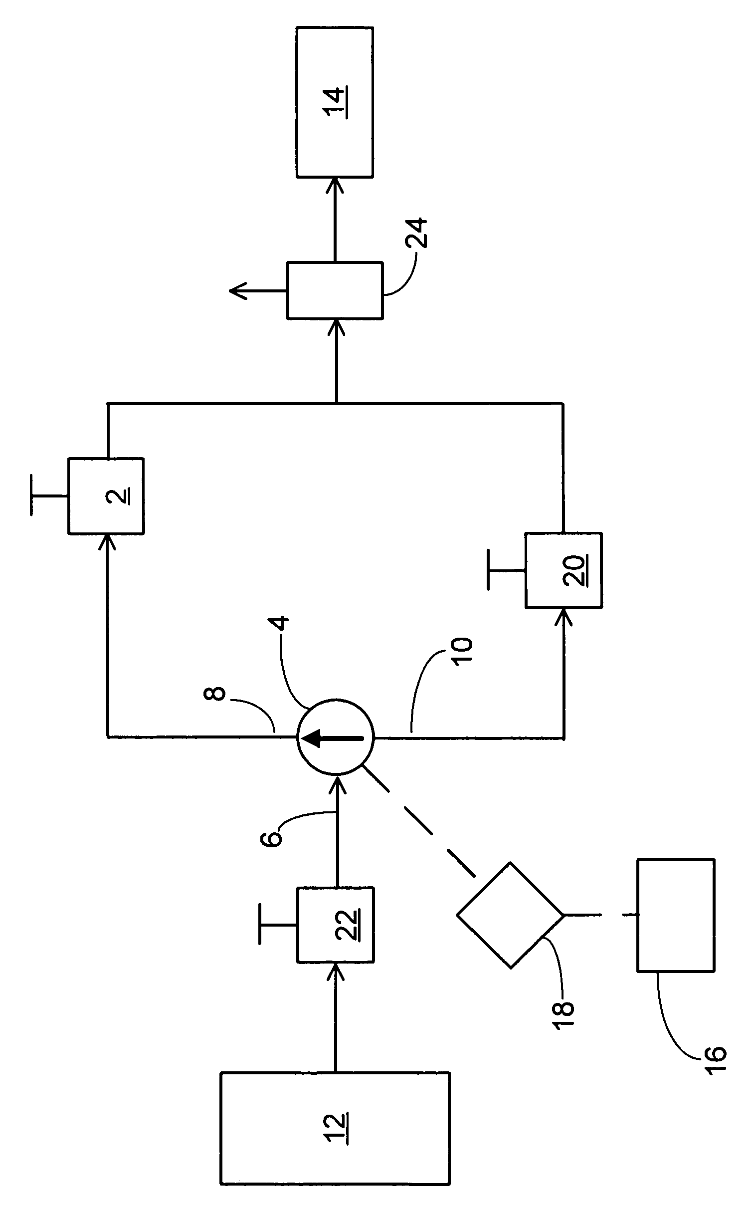
[0016] In an embodiment of a blow air control system according to the present invention, shown in the FIGURE, a three-way valve 4 can control whether high pressure gas flows into an injection nozzle 14 or whether low pressure gas flows into the injection nozzle 14. A three-way valve 4 includes valves having a common port 6 and two or more selectable ports in which any one of the selectable ports can be fluidly coupled to the common port 6. The three-way valv...


PUM

PropertyMeasurementUnit
timeaaaaaaaaaa
pressureaaaaaaaaaa
pressureaaaaaaaaaa

Abstract

Blow air control systems control injecting a first gas at a first pressure into the interior of a parison and then injecting a second gas at a second pressure greater than the first pressure into the interior of the parison in blow-molding a container.

Description

FIELD OF THE INVENTION [0001] The present invention relates to a blow air control system, which can be used as a component of a blow molding system. More particularly, the invention is a network including a valve and a regulator for injecting air at a low pressure into a parison and for injecting air at a high pressure into a parison. DESCRIPTION OF THE RELATED ART [0002] Blow molding systems can inflate a parison by pushing an injection nozzle into the parison and injecting air through the nozzle into the interior of the parison. The parison can be inflated so that the exterior surface of the parison presses against a mold, and the parison assumes the shape of the mold. Pressing the parison exterior surface against the mold can also facilitate cooling of the parison through conduction of heat from the parison through the mold. It can be useful to use a high pressure to inflate the parison, so that the parison exterior surface presses firmly against the mold and assumes the shape of...

Claims


Application Information

Patent Timeline
Patent Type & Authority Applications(United States)
IPC IPC(8): B29C49/00
CPCB29C49/16B29C49/18B29C49/46B29C49/783B29C2049/6646B29C49/4289B29C2049/7831B29C2049/7832B29C2049/78805
Inventor CRIDER, MATTHEWKELLY, MICHAEL J.
Owner GRAHAM PACKAGING CO LP
Why Eureka
Try Eureka