

Flat panel display
a flat panel display and display panel technology, applied in non-linear optics, instruments, optics, etc., can solve the problems of reducing brightness, bulky volume, poor brightness, etc., and achieve the effect of reducing assembly time, maintaining optical performance and image quality, and optimizing optical performan
- Summary
- Abstract
- Description
- Claims
- Application Information
AI Technical Summary
Benefits of technology
Problems solved by technology
Method used
Image

Examples
first embodiment
The First Embodiment
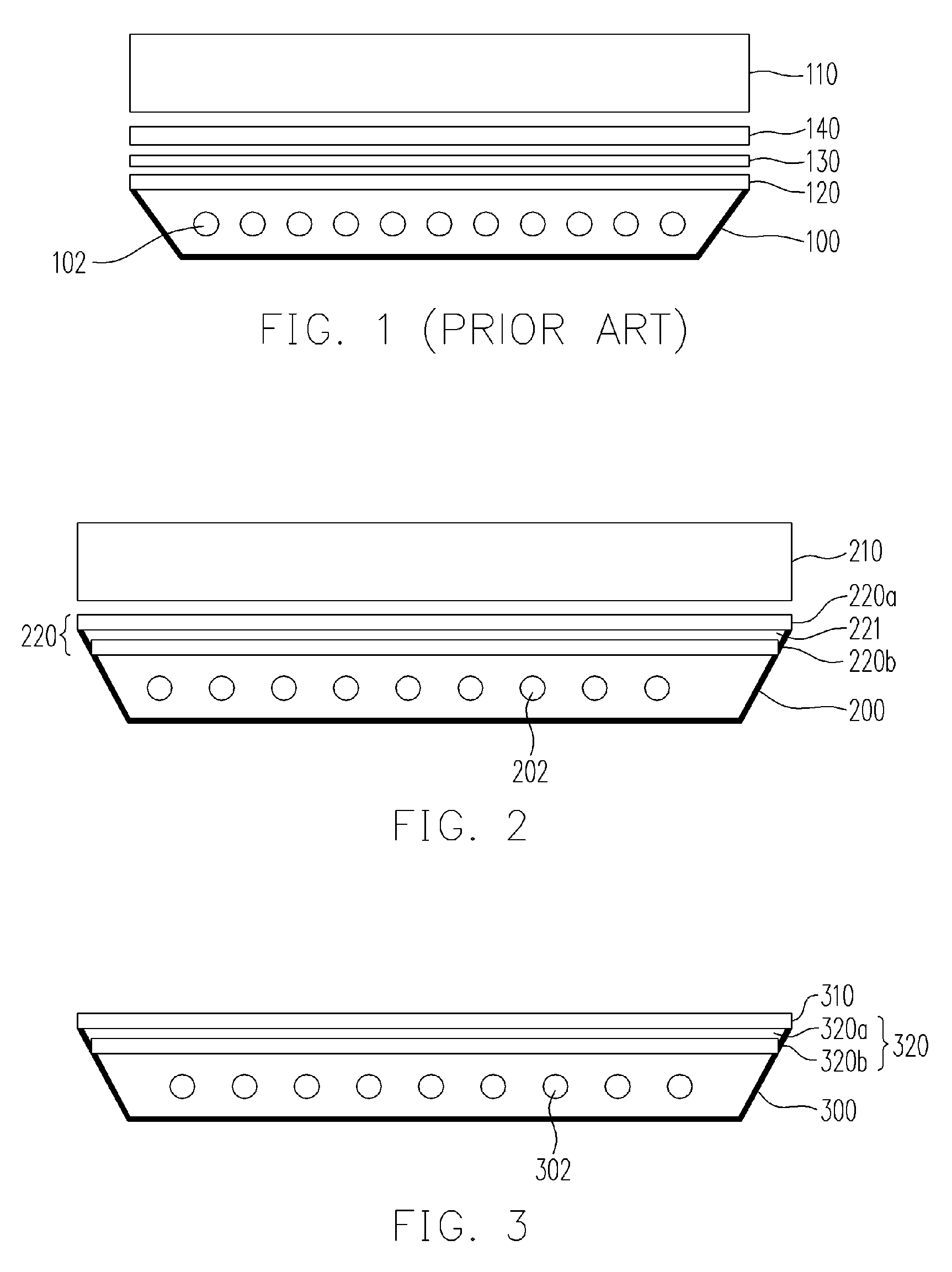
[0042]FIG. 2 is a cross sectional view of a flat panel display of one embodiment of the present invention. Referring to FIG. 2, the flat panel display comprises a backlight module 200, a complex diffuser plate or a brightness enhancement diffuser plate (BEDP) 220 (including 220a and 220b) disposed on the backlight module 200 and an LCD panel 210, wherein the LCD panel 210, is disposed over the backlight module 200. Furthermore, the backlight module 200 comprises a light source 202, a reflector sheet (not shown) for masking the light source 202, and the complex diffuser plate 220 that comprises a first diffuser layer 220a and a second diffuser layer 220b separated from the first diffuser layer 220a with a first air layer 221. The first diffuser layer 220a and the second diffuser layer 220b are combined to each other, and the first diffuser layer 220a is adjacent to the liquid crystal display panel 210, the second diffuser layer 220b is adjacent to the first diffus...
second embodiment
The Second Embodiment
[0050]FIG. 3 is a cross sectional view of a flat panel display of another embodiment of the present invention. Referring to FIG. 3 the flat panel display comprises a backlight module 300, a complex diffuser plate 320 (including 320a and 320b) disposed on the backlight module 300 and an LCD panel 310, wherein the LCD panel 310, is disposed over the backlight module 300. Furthermore, the backlight module 300 comprises a light source 302, a reflector sheet (not shown) for masking the light source 302, and the complex diffuser plate 320 that comprises a first diffuser layer 320a and a second diffuser layer 320b. The first diffuser layer 320a and the second diffuser layer 320b are combined or embedded to each other, and the first diffuser layer 320a is adjacent to the liquid crystal display panel 310, the second diffuser layer 320b is adjacent to the first diffuser layer 320a. Moreover, the first diffuser layer 320a and the second diffuser layer 320b have different r...
third embodiment
The Third Embodiment
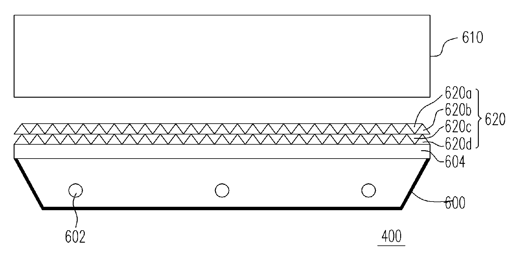
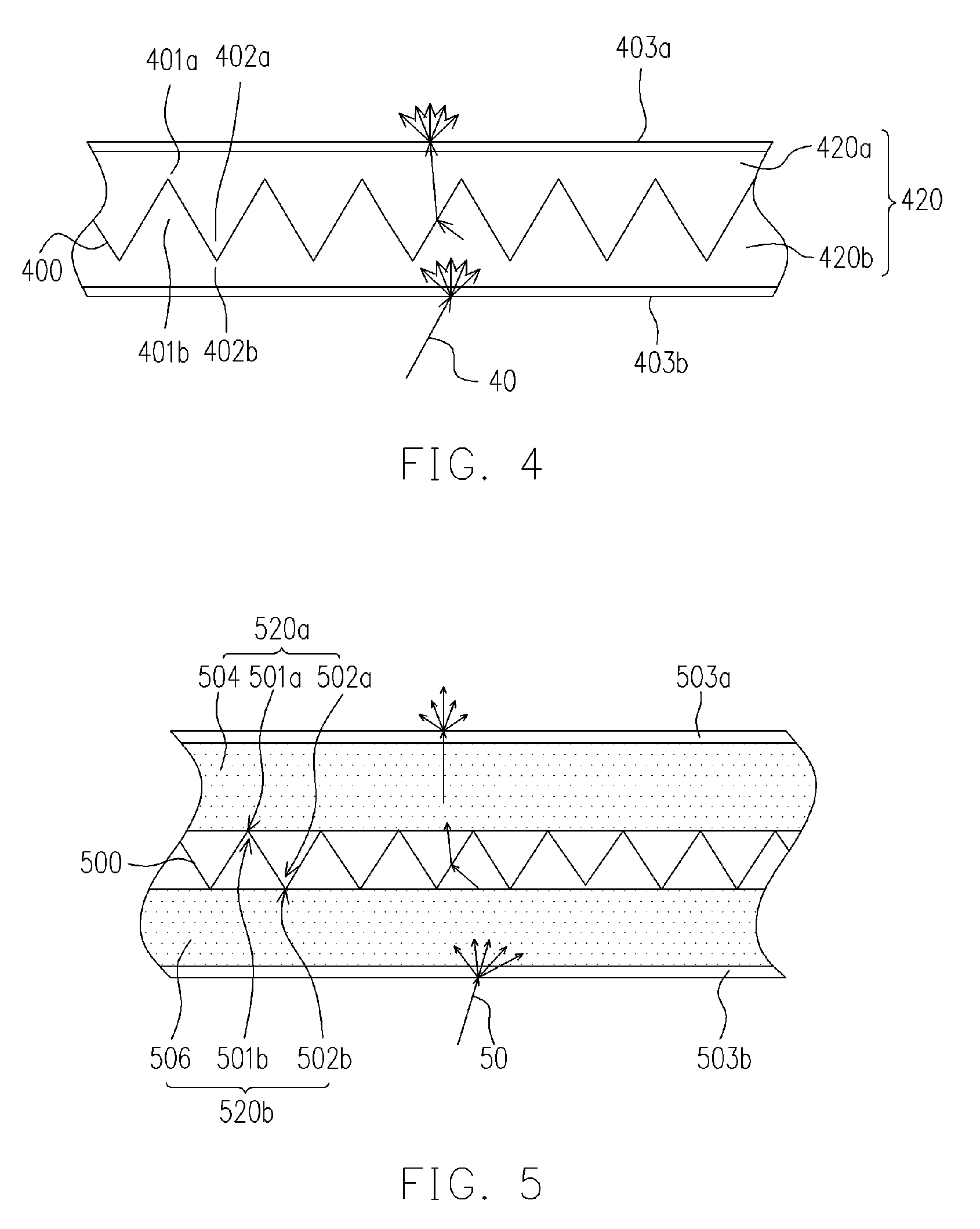
[0051]FIG. 4 is a cross sectional enlarged view of the complex diffuser plate 320 of a flat panel display in FIG. 3, and the complex diffuser plate is renumbered as 420 for according to FIG. 4. The complex diffuser plate 420 comprises a first diffuser layer 420a and a second diffuser layer 420b. The first diffuser layer 420a includes a first recess 401a and a first protrusion 402a and the second diffuser layer 420b includes a second recess 402b and a second protrusion 401b, wherein the first recess 401a and the second protrusion 401b are embedded to each other, and the second recess 402b and the first protrusion 402a are embedded to each other as well. The embedding interface 400 between the first diffuser layer 420a and the second diffuser layer 420b may be a prism interface as shown in FIG. 4, or a simple geometric surface, a wavy surface, a Fourier series curve surface, a fractal curve surface and one of other nonlinear adjacent to shape surfaces.
[0052] The s...
PUM
 Abstract
Description
Claims
Application Information