Instrument for cryogenic treatments in the medical, paramedical and cosmetic field

a technology for instruments and cryogenic treatments, applied in the field of instruments for cryogenic treatments in the medical, paramedical and cosmetic field, can solve the problems of blocking the microapplicator, two main and almost prohibitive difficulties, and affecting the effect of cryogenic treatment

Inactive Publication Date: 2006-09-07
N V H & O EQUIP
View PDF13 Cites 72 Cited by
  • Summary
  • Abstract
  • Description
  • Claims
  • Application Information

AI Technical Summary

Problems solved by technology

Two main and almost prohibitive difficulties appear during the implementation of this technique.
Indeed, it seems that impurities, essentially solid microparticles, are also present in the jet and they quickly cause clogging...

Method used


Image

  • Instrument for cryogenic treatments in the medical, paramedical and cosmetic field
  • Instrument for cryogenic treatments in the medical, paramedical and cosmetic field
  • Instrument for cryogenic treatments in the medical, paramedical and cosmetic field

Examples


Embodiment Construction

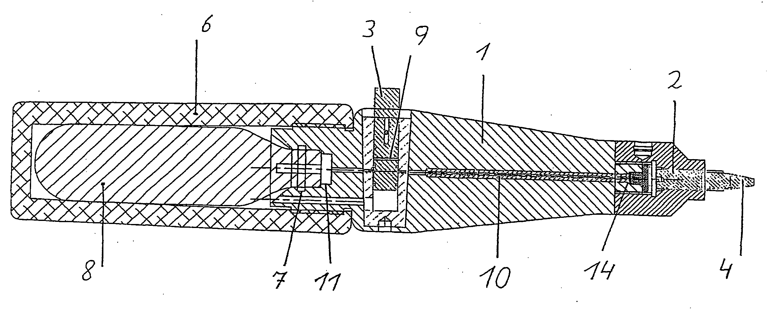
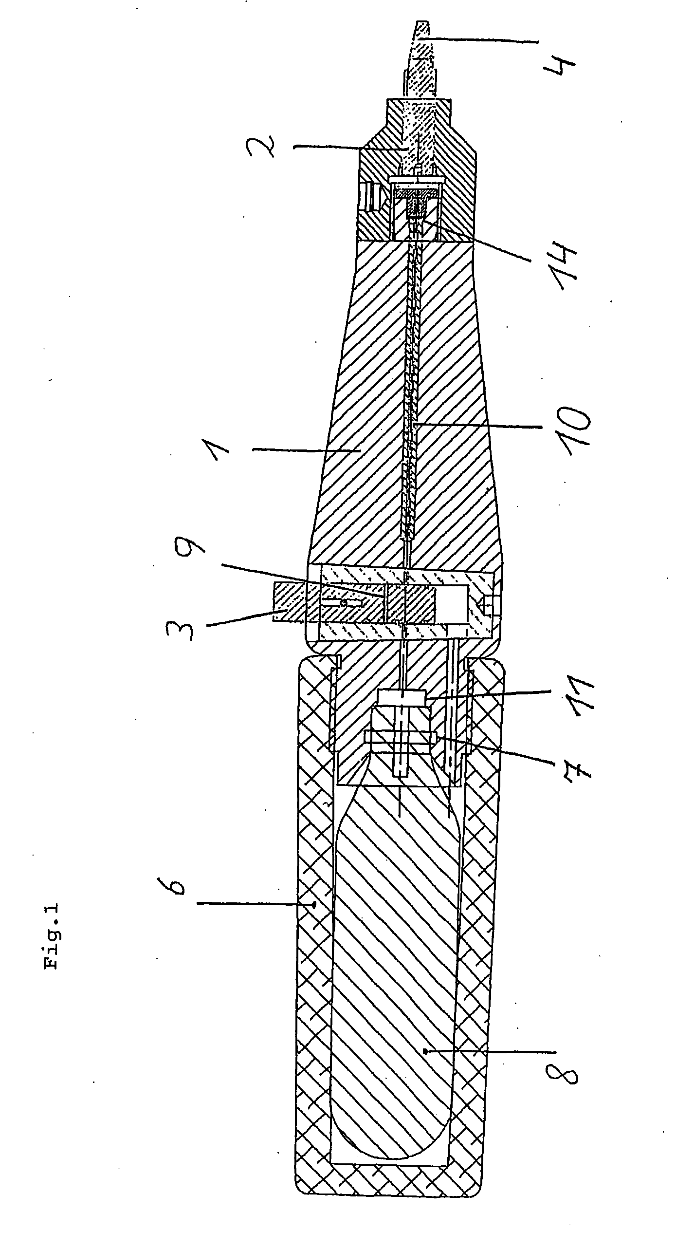
[0033] The apparatus for cryogenic treatment comprises a body 1. On this body, a microapplicator 2, protected with a cover when not in use, is fixed in an impervious but removable manner.

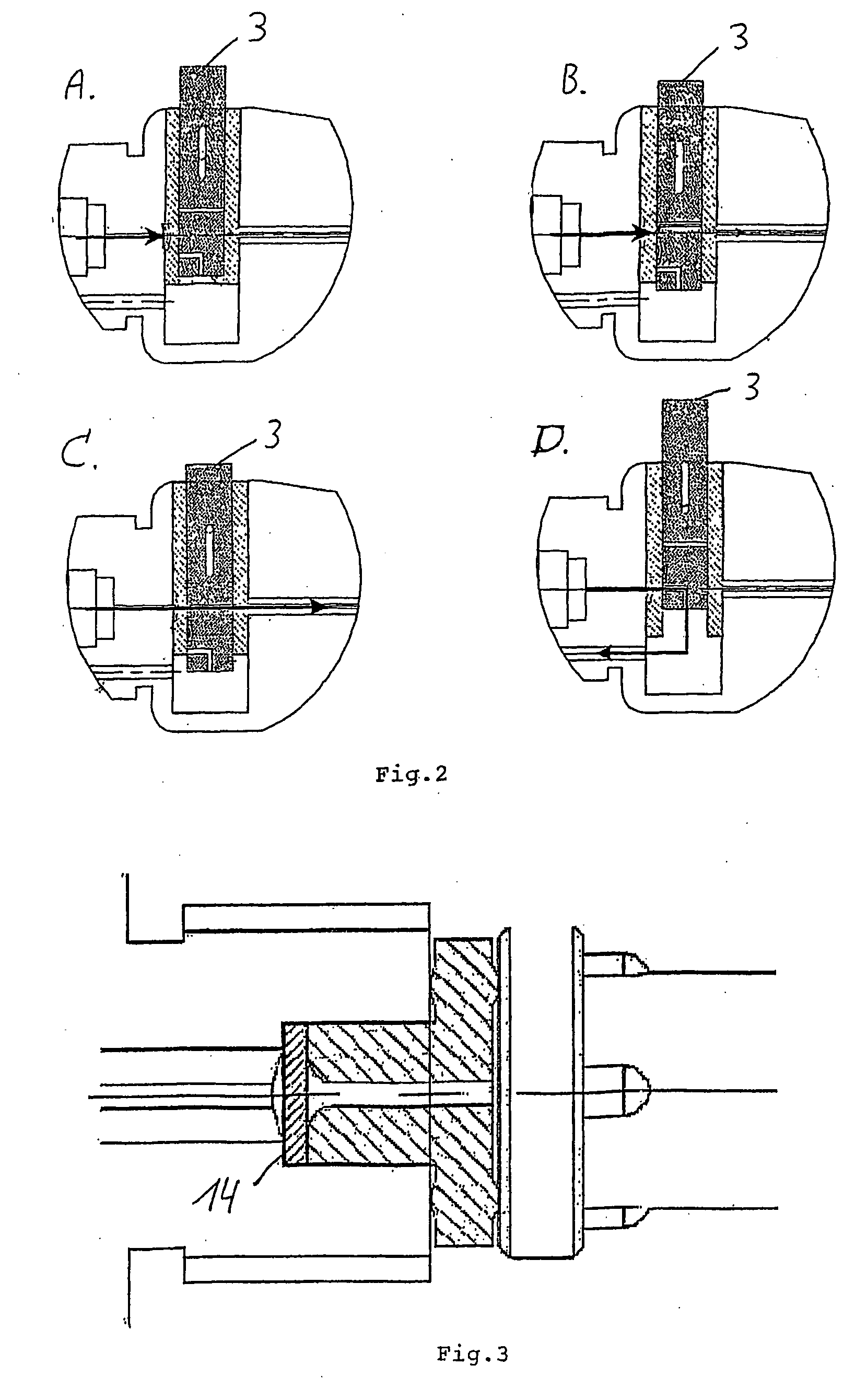
[0034] On the back of the body 1, an insertion tube 6 is mounted. It can receive a condensed gas cartridge 8. An O-ring 7 creates an impervious connection between the cartridge and the body 1. In use, when the cartridge 8 is in place, the mounting of the insertion tube 6 on the body 1 causes the perforation of a protective cap 11 that closes up the cartridge 8 and permits so the communication through the pipe 10 between the cartridge 8 and the microapplicator 2 through a valve 3.

[0035] The microapplicator 2 has a bore diameter 4 of between about 20 to 120 μm, preferably of between about 35 to 80 μm. It is attached to a longitudinal pipe 10 with filter 14 interposed therebetween, preferably maintained in place on the front removable part and more specific at the back of the microapplicator 2.

[0036...


PUM


Abstract

The invention concerns an instrument suited for cryogenic treatments, for the medical or paramedical field as well as for the cosmetic field, comprising a microapplicator having a bore on the order of 20 to 120 μm supplied with a gas stream wherein all the foreign particles above 3 μm and preferably above 1 μm are eliminated. The invention also concerns a microapplicator designed to be used in such an instrument provided with a filter housed in or on said microapplicator, so that each time the latter is replaced, the filter is also replaced.

Description

FIELD OF THE INVENTION [0001] The present invention concerns an apparatus, which can be used for various cryogenic treatments as well in the medical or paramedical sector as in the cosmetic sector. STATE OF THE ART [0002] Numerous dermatological diseases are currently treated with the cryogenic method by using a “jet” of gas, generally nitrous oxide (N2O) at very low temperature. This cryotechnology is also used in other medical disciplines and in cosmetic fields. [0003] An instrument, among other things, is used, in which a cartridge of liquefied gas, for example N2O, is introduced, which communicates, generally by perforating a membrane or a protective cap, with a microapplicator in the form of a needle with a very small bore diameter, the whole being contained in a needle cover held by the operator's hand. [0004] Other gas than N2O (laughing gas) can of course be used. [0005] The gas, contained in a liquid state in the cartridge in the form of gas, is expanded by the release of a...

Claims


Application Information

Patent Timeline
IPC IPC(8): A61B18/02
CPCA61B18/0218A61B2018/0231
Inventor HERMANS, ERIK
Owner N V H & O EQUIP
Why Eureka
Try Eureka