
Driving evaluation system and server

a technology of evaluation system and driver, applied in the direction of navigation instruments, pedestrian/occupant safety arrangements, instruments, etc., can solve the problems of burdening the driver, taking time for the driver to learn proper driving operations,

Active Publication Date: 2006-09-07
DENSO CORP
View PDF10 Cites 35 Cited by
  • Summary
  • Abstract
  • Description
  • Claims
  • Application Information

AI Technical Summary

Benefits of technology

[0006] The present invention has been achieved in view of the problems. It is an object of the present invention to provide a technique capable of making a driver easily recognize driving operations and physical operations to be learned and also easily recognize correction amounts on the operations. As a result, this technique is capable of shortening time necessary for the driver to learn proper driving operations and physical operations.

Problems solved by technology

However, this apparatus does not notify of specific driving operations and physical operations the driver has to learn at time points during driving and necessary correction amounts in the operations.
It places a burden on the driver and there is also a problem that it takes time for the driver to learn proper driving operations and physical operations.

Method used


Image

  • Driving evaluation system and server
  • Driving evaluation system and server
  • Driving evaluation system and server

Examples


first embodiment

[0080] 1. First Embodiment

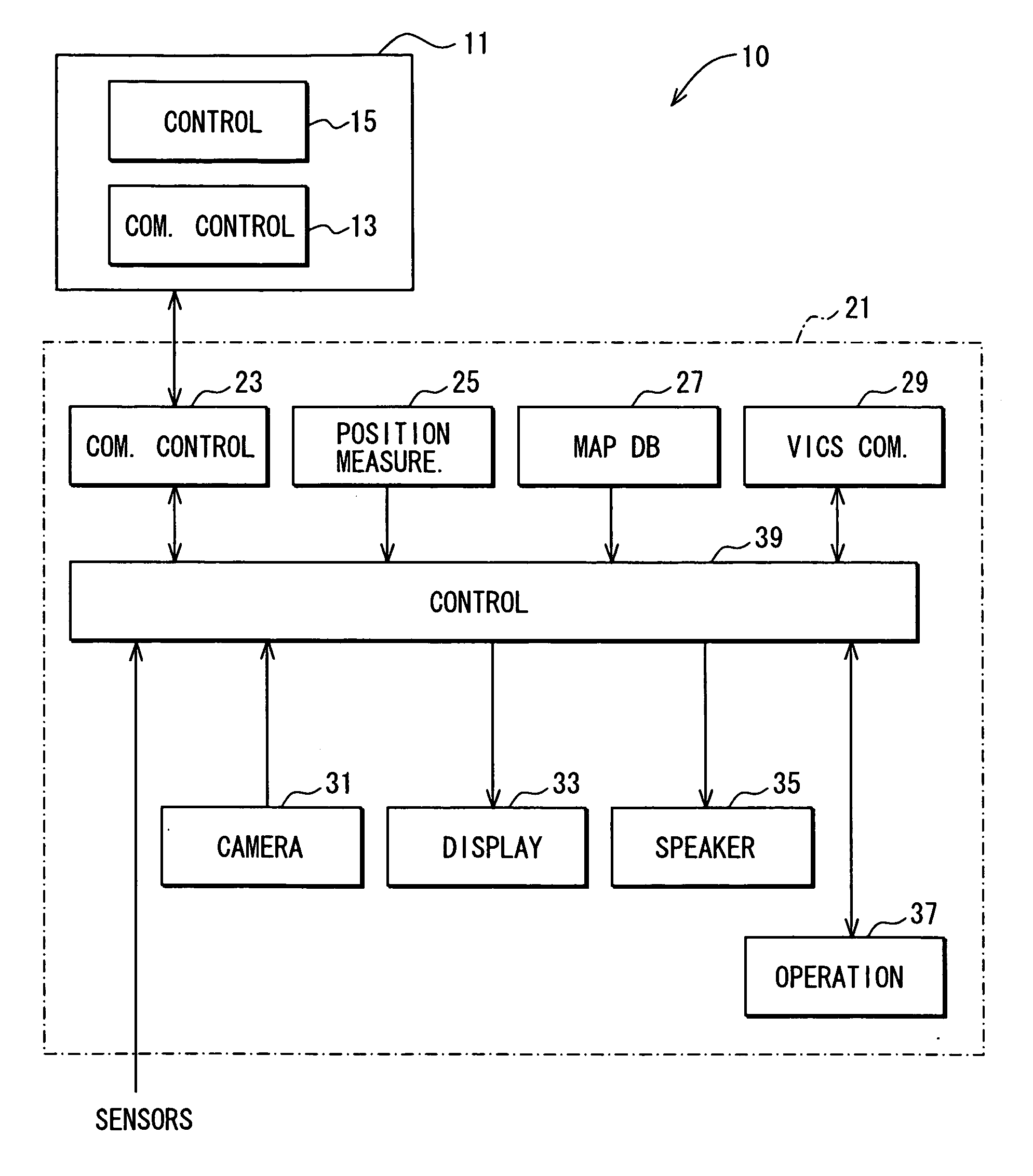
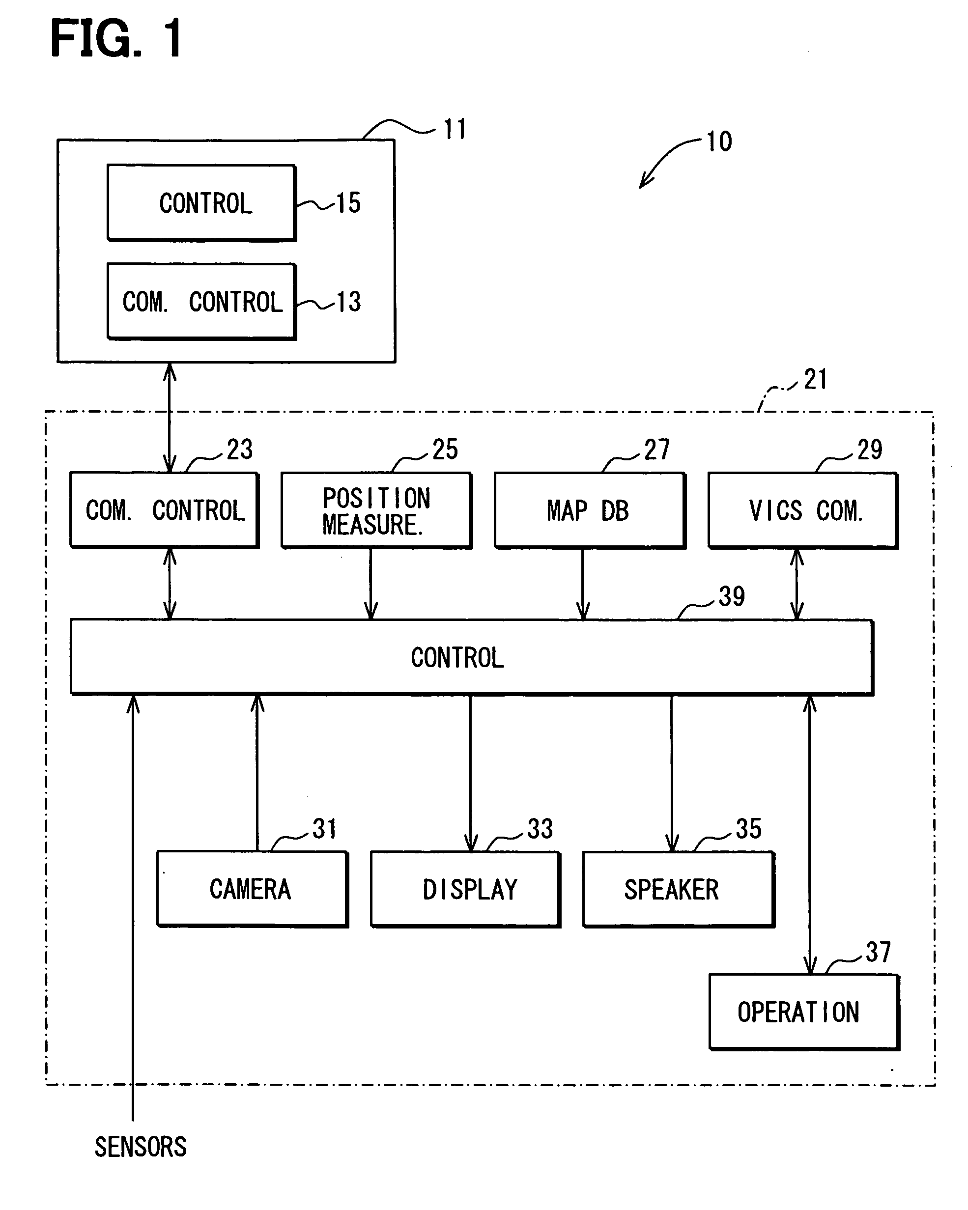
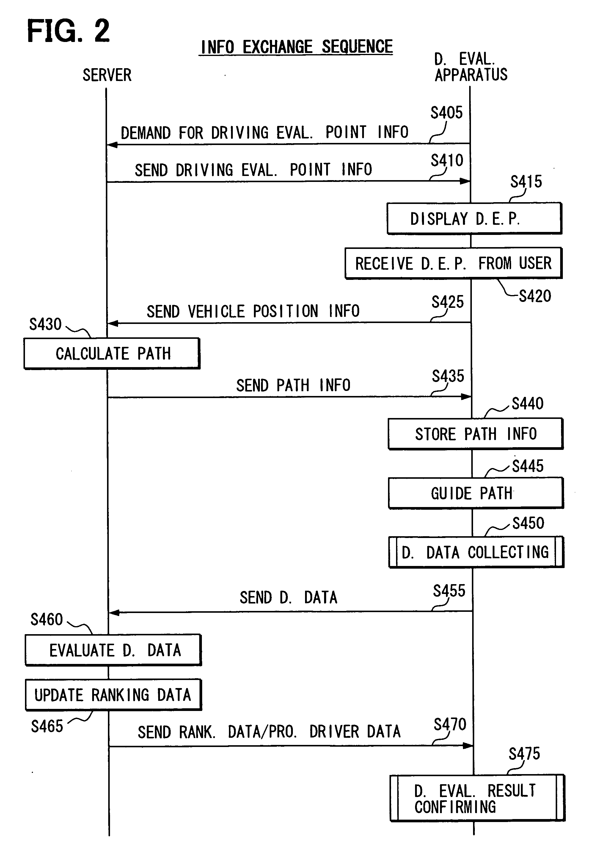
[0081] A first embodiment will be described. FIG. 2 is a sequence diagram of information exchange between the driving evaluation apparatus 21 and the server 11. First, when the operation unit 37 receives an instruction to make a driving evaluation from the driver of a vehicle on which the driving evaluation apparatus 21 is mounted (hereinbelow, simply called “driver”), the driving evaluation apparatus 21 demands the server 11 for driving evaluation point information via the communication control unit 23 (S405).

[0082] When the demand is received from the driving evaluation apparatus 21, the server 11 sends the driving evaluation point information stored in the control unit 15 to the driving evaluation apparatus 21 (S410).

[0083] On receipt of the driving evaluation point information from the server 11, the driving evaluation apparatus 21 displays the driving evaluation point on the display 33 (S415). In a display example shown in FIG. 3A, multiple marks 610...

second embodiment

[0105] 2. Second Embodiment

[0106] A second embodiment will now be described. FIG. 8 is a sequence diagram of information exchange between the driving evaluation apparatus 21 and the server 11 in the second embodiment. First, when the operation unit 37 accepts information of a destination from the driver (S500), the driving evaluation apparatus 21 requests the server 11 for the driving evaluation point information via the communication control unit 23 (S505).

[0107] The server 11 receives the request from the driving evaluation apparatus 21 and sends the stored driving evaluation point information to the driving evaluation apparatus 21 (S510).

[0108] The driving evaluation apparatus 21 receives the driving evaluating point information from the server 11 and calculates some candidate paths including a path extending through the driving evaluation point (S515). The calculation of paths is executed by using the widely known Dijkstra method or the like in consideration of traffic informa...


PUM


Abstract

Travel information of a target vehicle is stored in time sequence and, on the basis of the travel information and pre-stored travel information of a professional driver's vehicle, a travel position of the target vehicle and a travel position of the professional driver's vehicle are displayed in animation. In such a manner, the driver can visually recognize the travel positions of the displayed target vehicle and the reference vehicle and understand how much the target vehicle is deviated from the ideal travel position.

Description

CROSS REFERENCE TO RELATED APPLICATIONS [0001] This application is based on and incorporates herein by reference Japanese Patent Application No. 2005-57395 filed on Mar. 2, 2005. FIELD OF THE INVENTION [0002] The present invention relates to a driving supporting system for improving driving techniques. BACKGROUND OF THE INVENTION [0003] In recent years, demands for developing safety techniques in vehicles are changing from the viewpoint of assuring safety at the time of occurrence of an accident to the viewpoint of preventing occurrence of an accident. As one of methods for preventing occurrence of an accident, various driving evaluation apparatuses for improving driving techniques are proposed. For example, a driving evaluation apparatus disclosed in Patent Document 1 measures driving operations (operations on the steering wheel, pedal, gear, winker, and the like) of the driver, physical operations (sight line movement, confirming operation, and the like), physiologic data (cardiac...

Claims


Application Information

Patent Timeline
IPC IPC(8): G06F19/00B60R21/00G08G1/00G09B9/042G09B29/00G09B29/10
CPCG09B9/05G09B9/052
Inventor YOSHIDA, ICHIROTAKI, MASAYUKI
Owner DENSO CORP
Learn More