Drive-permission apparatus

Inactive Publication Date: 2006-09-14
DENSO CORP +1
View PDF15 Cites 10 Cited by
  • Summary
  • Abstract
  • Description
  • Claims
  • Application Information

AI Technical Summary

Benefits of technology

[0012] The present invention has been accomplished in view of the above-mentioned problems and it is an object of the invention to provide a drive-permission apparatus for controlling the operation of a motor-drive

Problems solved by technology

However, when there is no mechanical connection between the shift range setting means and the shift range switching mechanism, it is likely that the shift range switching c

Method used


Image

  • Drive-permission apparatus
  • Drive-permission apparatus
  • Drive-permission apparatus

Examples


Example

[0036] In this first embodiment the drive-permission apparatus of this embodiment is applied to a vehicle on which is installed a shift range switching system in a vehicular automatic transmission. Reference will be made first to the shift range switching system.

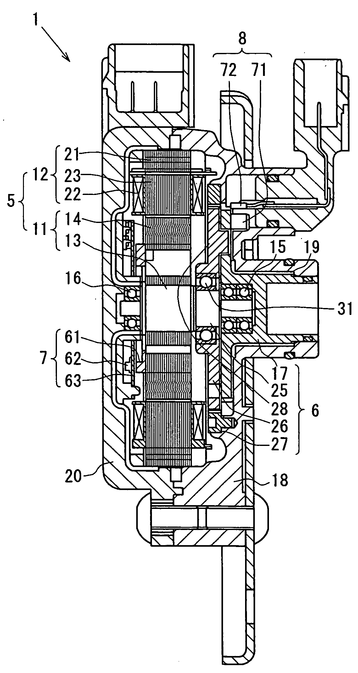
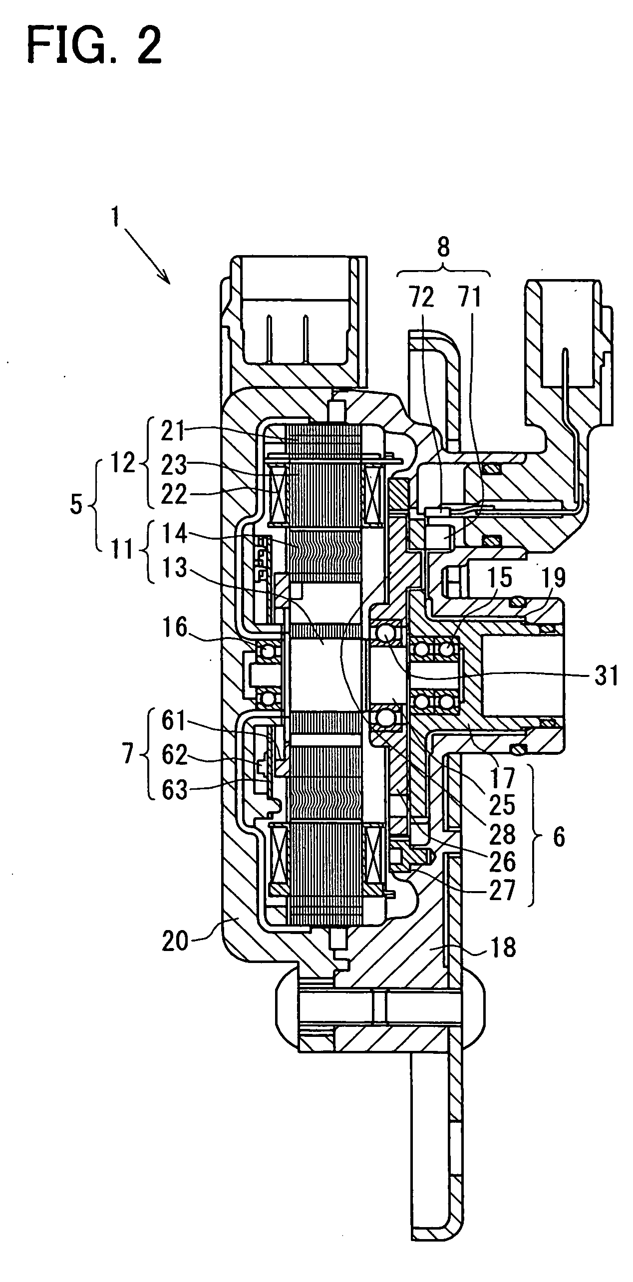
[0037] The shift range switching system includes a rotary actuator 1 (see FIG. 2; an example of a motor-driven actuator) to operate a shift range switching mechanism 3 (including a parking switching mechanism 4; see FIG. 4; an example of a drive object) mounted in a vehicular automatic transmission 2 (see FIG. 3).

[0038] The rotary actuator 1, which is a servo mechanism for driving the shift range switching mechanism 3, includes a synchronous electric motor 5, a reduction gear 6 for reducing a rotational output of the electric motor 5 and driving the shift range switching mechanism 3, an encoder 7 for detecting a rotational angle of the electric motor 5, and output angle detecting means (an example of angle detecting means ...


PUM


Abstract

An ECU controls a starter relay. Output angle detector detects a rotational angle of an output shaft in a rotary actuator. The ECU stores a first rotational angle which is detected by the output angle detector when a starting switch is OFF. When the starting switch is ON and when the difference between a second rotational angle detected at that time by the output angle detector and the first rotational angle already stored is not within a certain value, the ECU inhibits the operation of the starter relay to inhibit engine start.

Description

CROSS REFERENCE TO RELATED APPLICATIONS [0001] This application is based on Japanese Patent Applications No. 2005-35050 filed on Feb. 10, 2005, the disclosure of which is incorporated herein by reference. FIELD OF THE INVENTION [0002] The present invention relates to a drive-permission apparatus. Particularly, the present invention is concerned with a technique suitable for use in an apparatus wherein the operation of a motor-driven actuator (a rotary actuator) is controlled in accordance with a command signal (e.g., a command signal issued by operating means or by control means). [0003] Specifically, the present invention pertains to a technique suitable for use in an apparatus wherein operating means (e.g., a shift lever) and a drive object (e.g., a shift range switching mechanism) which executes the contents of operation performed by the operation means are not mechanically connected with each other. BACKGROUND OF THE INVENTION [0004] As an example of the background technique rel...

Claims


Application Information

Patent Timeline
IPC IPC(8): F16D27/00B60W10/04B60W10/06B60W10/10F02D29/00F02D29/02F16H61/28
CPCF02N11/103F02P2017/125F16H59/10F16H61/16F16H61/32F16H2061/326
Inventor HORI, MASASHISHINOJIMA, MASAAKIKIMURA, KIYOSHIMATSUZAKI, HARUKIKASHIWAGI, TOMOYUKI
Owner DENSO CORP
Why Eureka
Try Eureka