Power supply for underground and pad mounted power distribution systems

a power distribution system and power supply technology, applied in the field of power supplies, can solve the problems of large standard transformers to convert high voltage into low voltage for this equipment, high installation cost, and inability to meet the needs of underground vaults or pad mounted compartments,

Active Publication Date: 2006-09-14
LINDSEY MFG
View PDF9 Cites 30 Cited by
  • Summary
  • Abstract
  • Description
  • Claims
  • Application Information

AI Technical Summary

Problems solved by technology

Monitoring and controlling these high voltage segments of the system in underground vaults or pad mounted compartments poses the problem of finding a lower voltage power supply for the switching and monitoring equipment.
This type of power supply is not typically available in the underground vaults or pad mounted compartments where the high voltage lines run.
A standard transformer to convert the high voltage into a lower voltage for this equipment is large, expensive and time consuming to install, requiring modification of the existing high voltage lines and possibly of the underground vault or pad mounted compartment.

Method used


Image

  • Power supply for underground and pad mounted power distribution systems
  • Power supply for underground and pad mounted power distribution systems
  • Power supply for underground and pad mounted power distribution systems

Examples


Embodiment Construction

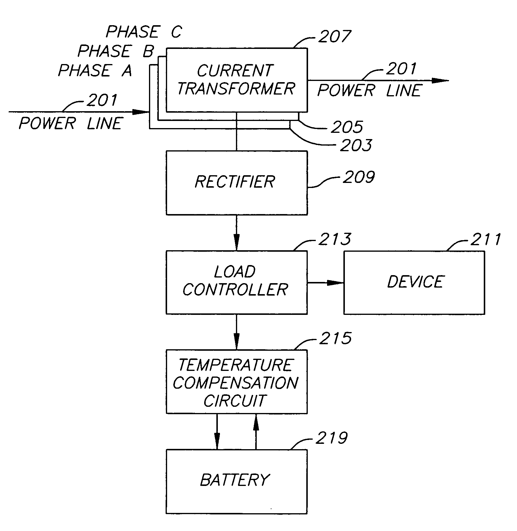
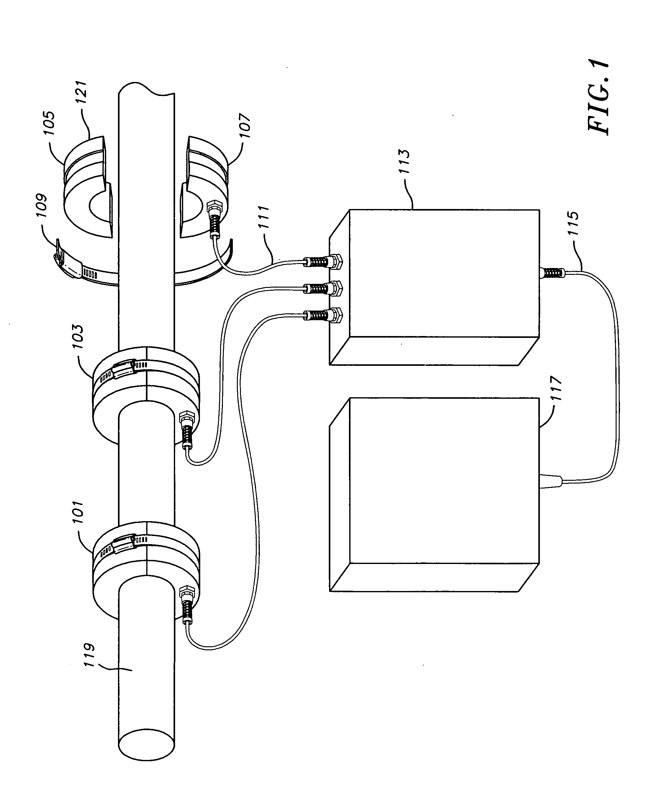
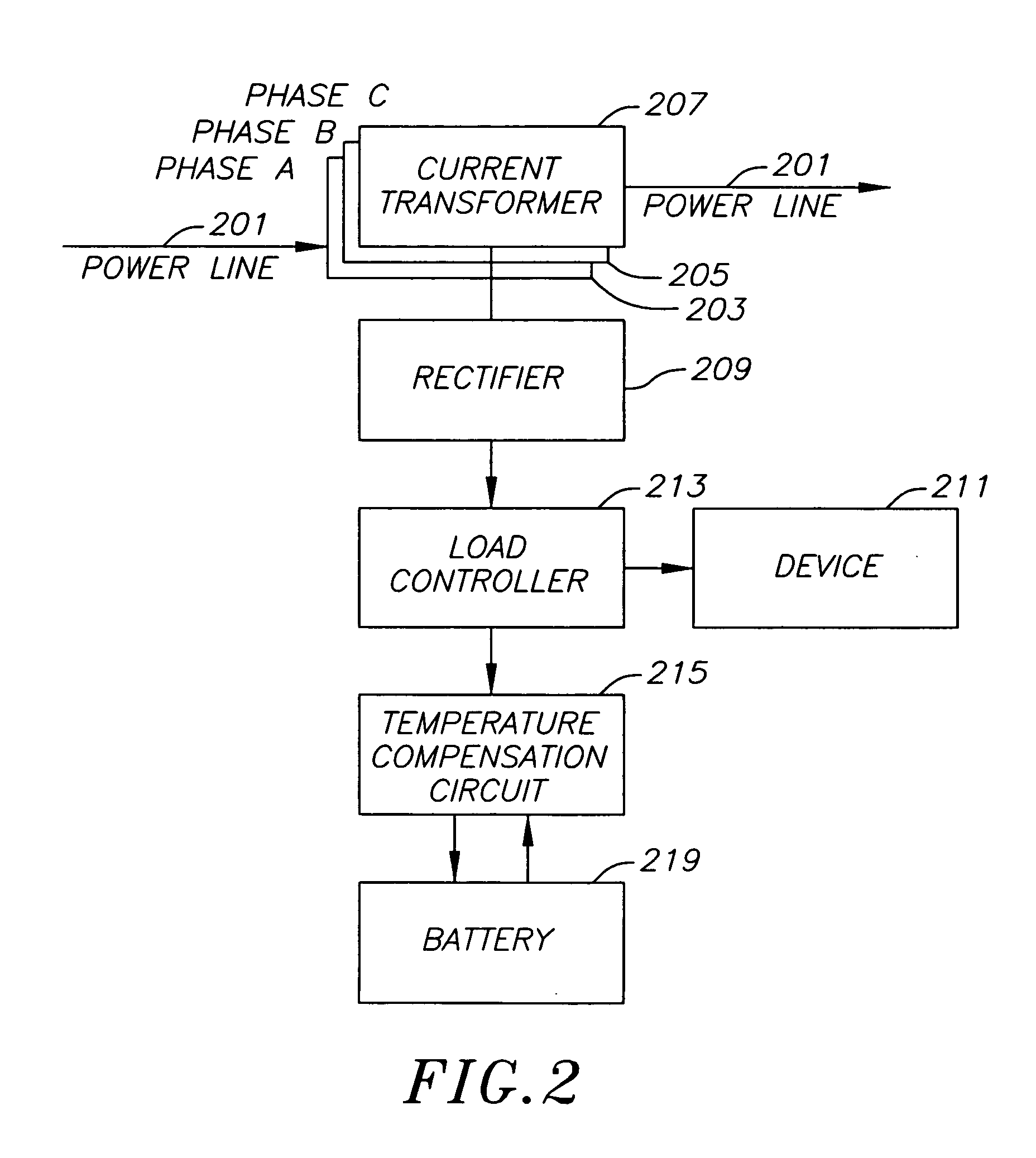
[0012]FIG. 1 is a diagram of one embodiment of a current transformer power supply. In one embodiment, the components of the power supply may be primarily in a housing 113. The housing 113 may be connected by a set of wires to individual current transformers 101, 103 and 105. The power supply may have any number of current transformers connected to it. In one embodiment, three current transformers, one for each of the phases of a primary power line may be used. In general, each additional current transformer increases the amount of power that may be output for a given current through the primary power line. The primary power line may be any single phase power cable, set of power cables, wire, set of wires or similar materials for transporting electricity encased in an insulating and protective material. In one embodiment, the power line may be a high voltage line.

[0013] In one embodiment, the current transformers may have an annular shape. The inner diameter may match or exceed the ...


PUM


Abstract

A power supply generated through a set of current transformers is disclosed. The current transformers may be removably attached to a primary power line such as a high voltage power line. The power supply may be used to power a device or charge a battery for a device that requires a low voltage input. The power supply may be used in underground vaults and pad mounted chambers that contain high voltage power lines. The power supply may generate a low voltage direct current out put that is not available in the vicinity of high voltage power lines in an underground vault or pad mounted chamber.

Description

FIELD OF INVENTION [0001] Embodiments of the invention relate to power supplies. The present invention relates to power supplies and more particularly to a power supply for underground and pad mounted power distribution systems. BACKGROUND OF THE INVENTION [0002] Electrical energy plays a central role in industrialized societies. The reliability of electric power systems is a critical factor in the planning, design and operation of power distribution systems. To ensure reliability, automated, real-time control of the system is desirable to allow for rapid response to the actual demand of electricity and any unforeseen contingencies such as equipment outages. [0003] Modernized power distribution networks typically utilize energy control centers to monitor and regulate network operation. Although these centers have greatly advanced in technology, their basic control objectives of economy and security remain the same. The economic goal is to minimize the cost of supplying the electrica...

Claims


Application Information

Patent Timeline
Patent Type & Authority Applications(United States)
IPC IPC(8): H02J7/00
CPCH02J7/025H02J5/005H02J11/00H02J7/0068H02J50/10
Inventor LINDSEY, KEITH E.STRIEZ, DUSANLANDES, JAMES L.
Owner LINDSEY MFG
Why Eureka
Try Eureka