System and method for determining illumination of a pixel by shadow planes

a shadow plane and luminance technology, applied in the field of graphics processing circuitry, can solve problems such as aliasing artifacts, luminance value is based, and luminance calculation methods

a shadow plane and luminance technology, applied in the field of graphics processing circuitry, can solve problems such as aliasing artifacts, luminance value is based, and luminance calculation methods

US20060202941A1Active Publication Date: 2006-09-14ATI TECH INC

Image

  • System and method for determining illumination of a pixel by shadow planes
  • System and method for determining illumination of a pixel by shadow planes
  • System and method for determining illumination of a pixel by shadow planes

Examples


Embodiment Construction

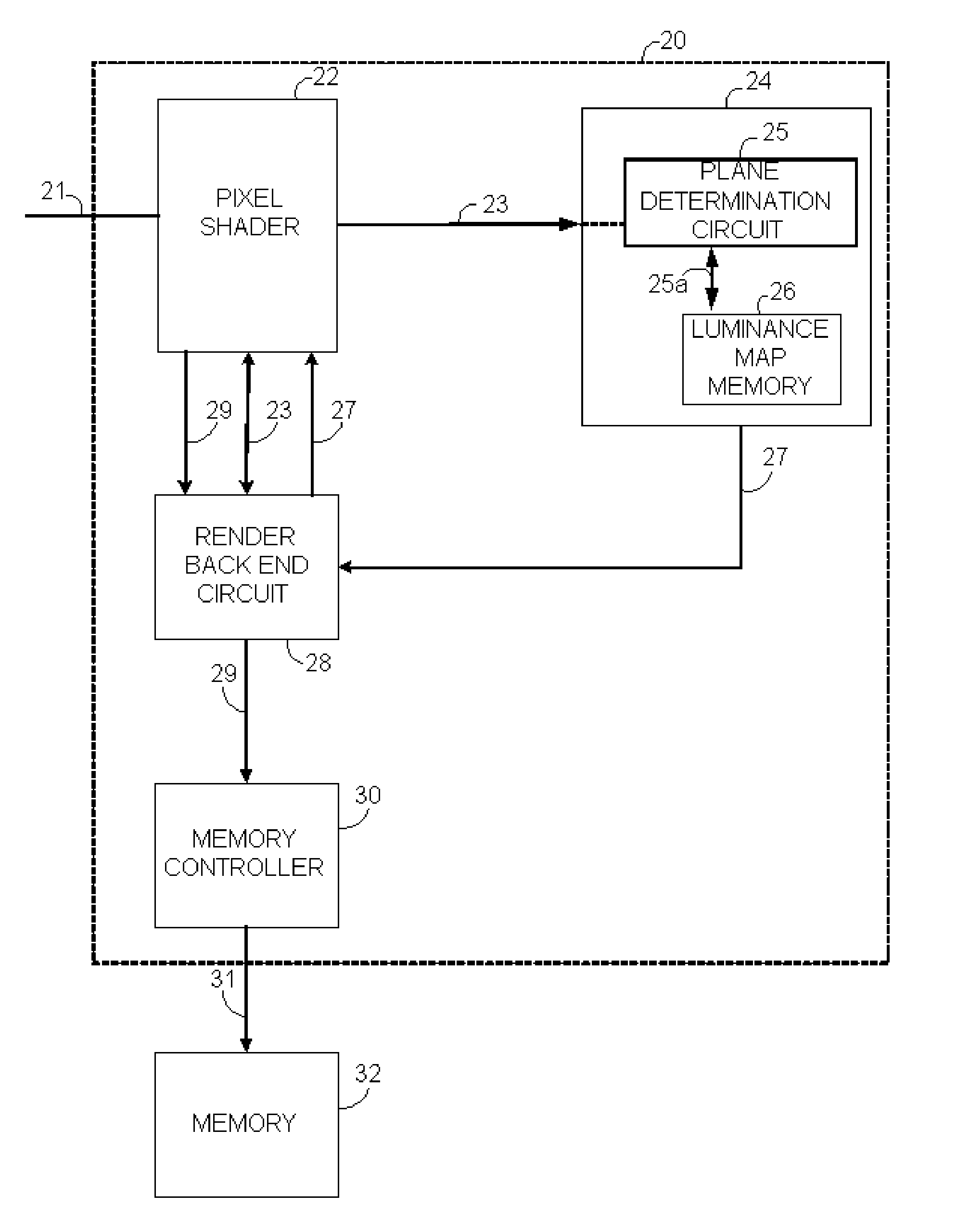
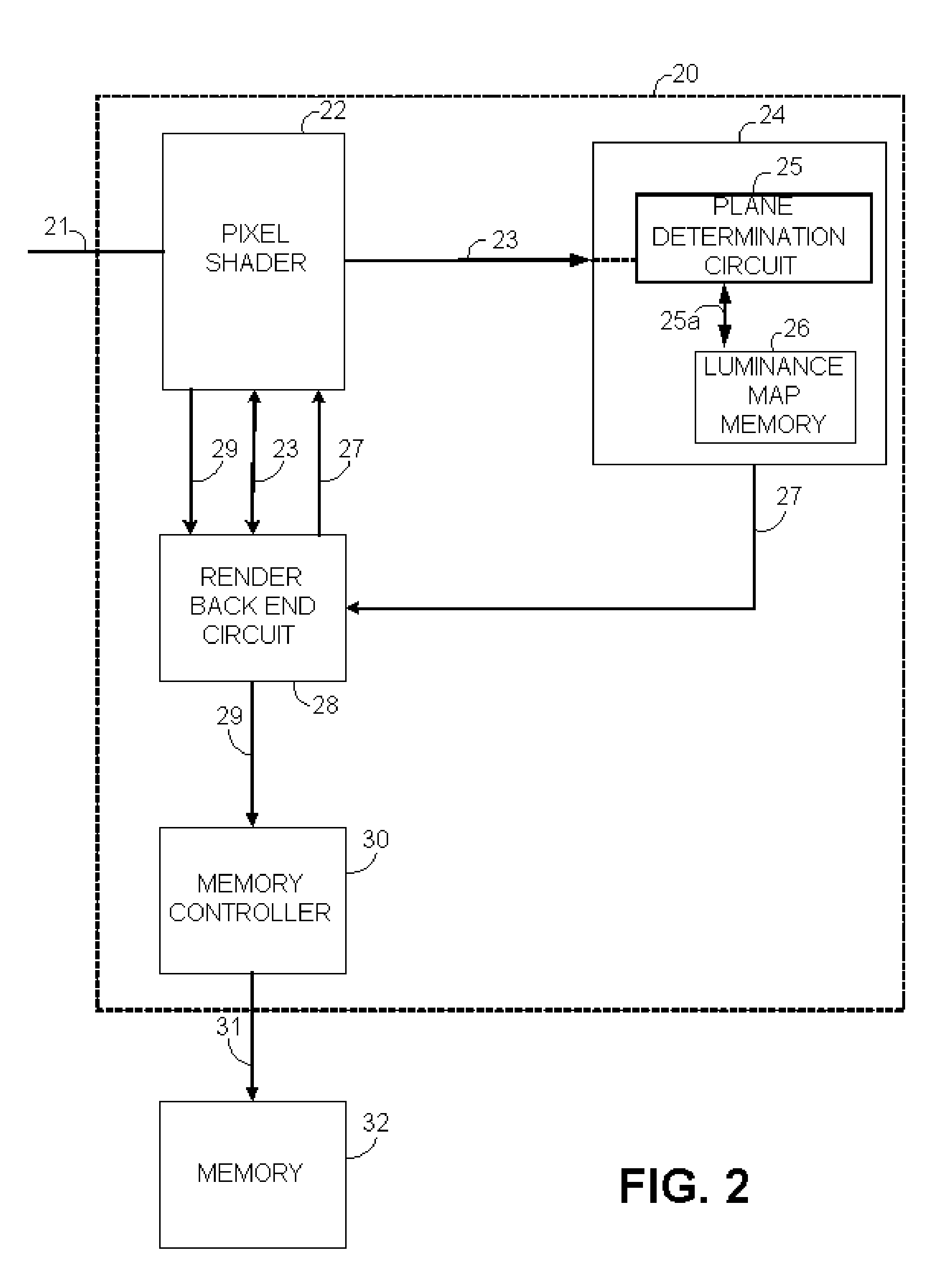
[0018] Briefly stated, a graphics processing circuit includes geometry processing logic, which determines the pixels covered by each primitive and a pixel shader operative to provide pixel color information in response to primitive data representing a scene to be rendered. A texture circuit is coupled to the pixel shader and supplies color values to the pixel shader for use in computing the pixel color. In this invention, the texture circuit is also operative to determine the luminance value to be applied to a pixel of interest based on the luminance values of pixels that define a plane including the pixel of interest. A render back end circuit is coupled to the pixel shader to combine pixel colors computed by the pixel shader with pixel values in memory. In this invention, it is also bound to the texture circuit, and is operative to provide the luminance value to the pixel of interest. Note that it is not required for the luminance logic described below to be implemented by placing...


PUM


Abstract

A graphics processing circuit includes a pixel shader operative to provide pixel color information in response to image data representing a scene to be rendered; a texture circuit, coupled to the pixel shader, operative to determine a luminance value to be applied to a pixel of interest based on the luminance values of the pixels that define a plane including the pixel of interest; and a render back end circuit, coupled to the texture circuit, operative to compute the luminance values from a shadow map that specifies the distance from the light source of the nearest object at a plurality of locations. A pixel illumination method includes receiving color information for a pixel to be rendered, defining a plane containing at least one pixel of interest, the plane including a plurality of planar values; comparing the plurality of planar values to a corresponding set of distance values; determining a luminance value for the at least one pixel of interest; and applying the luminance value to the at least one pixel of interest.

Description

FIELD OF THE INVENTION [0001] The present invention generally relates to graphics processing circuitry and, more particularly, to a system and method for determining the luminance of a pixel within an image. BACKGROUND OF THE INVENTION [0002] In computer graphics applications, complex shapes and structures are formed through the sampling, interconnection and rendering of more simple shapes, referred to as primitives. An example of such a primitive is a triangle, or other suitable polygon. These primitives, in turn, are formed by the interconnection of individual pixels. Objects are generated by combining a plurality of pixels together to form a shape (e.g. a cup). Physical attributes, such as color and texture are then applied to the individual pixels based on their location within the primitive and the primitives' orientation with respect to the generated shape. Several objects may be used to create a larger image. [0003] To enhance the presentation of the image, lighting (e.g. lum...

Claims


Application Information

Patent Timeline
14 Sep 2006
Publication
US20060202941A1
IPC
G09G3/36
CPC
G06T15/005; G06T15/50; G06T15/60; G06T15/80; G06T2215/12
Inventors
MOREIN, STEPHEN L.; SEILER, LARRY D.