Animated display calibration method and apparatus

a technology of display calibration and calibration method, applied in the direction of picture reproducers using projection devices, signal generators with optical-mechanical scanning, television systems, etc., can solve the problems of high degree of accuracy, difficult for a human to determine whether two similar shades of gray are present, and the like, and achieve high luminance (the amount of light). , the effect of enhancing details

Inactive Publication Date: 2006-09-14
PIXAR ANIMATION
View PDF12 Cites 24 Cited by
  • Summary
  • Abstract
  • Description
  • Claims
  • Application Information

AI Technical Summary

Benefits of technology

[0013] The herein described techniques and display are designed to give users the ability to match settings of the display equipment to settings used during production of a feature / content. This allows users to experience a feature how the director originally intended the content to be seen.
[0014] Through the use of various embodiments of the test patterns described herein, a user may adjust the display equipment settings for high fidelity playback. In some cases, these settings enhance details in the shadows, as well as areas with high levels of luminance (the amount of light in the picture.) Additionally, in some embodiments, proper display settings will produce a picture with subtle detail in both dark and light areas. Additionally, in some embodiments, after adjustment, the entire range of the picture, from the darkest to the brightest areas of the image should be observable. Additionally, in some embodiments, each successive step of increased brightness will have the correct relative relationship, ensuring a correct and consistent tonal scale.

Problems solved by technology

More specifically, the inventor realized that with static images, it is difficult for a human to determine whether two similar shades of gray, for example, appear different when displayed.
Because of this low accuracy, it has previously been difficult to readily calibrate displays driven by such DVD players, or the like, to a high degree of accuracy.
This was also very burdensome, thus consumers were not performing such calibrations.
For these reasons, and others, such packages do not appear to be widely used by consumers.

Method used


Image

  • Animated display calibration method and apparatus
  • Animated display calibration method and apparatus
  • Animated display calibration method and apparatus

Examples


Embodiment Construction

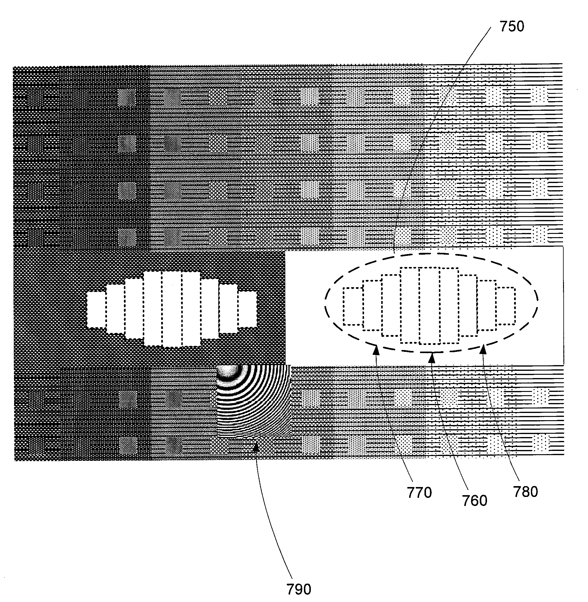
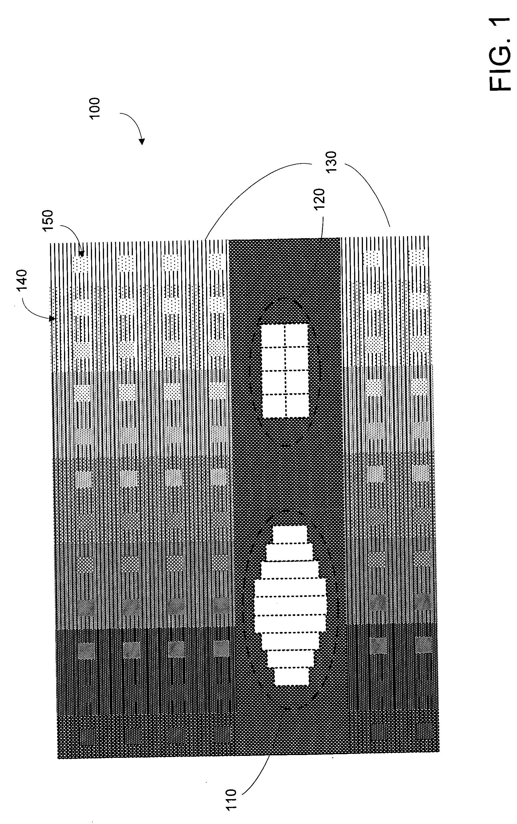
[0039]FIG. 1 illustrates a static calibration display 100 indicating a series of test calibration regions. As annotated in FIG. 1, the regions include a region 110 adapted to be used for calibrating a display black level; a region 120 adapted to be used for calibrating a display white clipping level; and regions 130 including ramps 140 and blocks 150 adapted to be used for calibrating a display gamma value. Static calibration display 100 is not within the prior art, and is referenced for purposes of terminology and understanding.

[0040] In the embodiment in FIG. 1, black optimize region 110 includes nine sub-regions (e.g. columns) of interest, however in other embodiments, a greater or lesser number of sub-regions are provided or are of interest. Additionally, in the example in FIG. 1, white check region 120 includes eight sub-regions (e.g. equally sized squares) of interest, however in other embodiments, a greater or fewer number of sub-regions can be used or are of interest. In va...


PUM


Abstract

A method for adjusting properties of a display includes displaying a first pluge image on the display to a user, wherein the display includes a plurality of locations, wherein the first pluge image comprises a first plurality of output values associated with the plurality of locations, thereafter displaying a second pluge image on the display to the user, wherein the second pluge image comprises a second plurality of output values associated with the plurality of locations, wherein the first plurality of output values are different from the second plurality of output values, and receiving a display adjustment input from the user, wherein the display adjustment input from the user is in response to the user viewing the first pluge image on the display and in response to the second pluge image on the display.

Description

BACKGROUND OF THE INVENTION [0001] The present invention relates to optical display calibration methods and apparatus. More particularly, the present invention relates to novel display calibration test patterns and methods of use. Applications may be applied to displays of any type of media, such as computer animated media. [0002] Throughout the years, movie makers have often tried to tell stories involving make-believe creatures, far away places, and fantastic things. To do so, they have often relied on animation techniques to bring the make-believe to “life.” Two of the major paths in animation have traditionally included, drawing-based animation techniques and stop motion animation techniques. [0003] Drawing-based animation techniques were refined in the twentieth century, by movie makers such as Walt Disney and used in movies such as “Snow White and the Seven Dwarfs” (1937) and “Fantasia” (1940). This animation technique typically required artists to hand-draw (or paint) animate...

Claims


Application Information

Patent Timeline
Patent Type & Authority Applications(United States)
IPC IPC(8): H04N11/20H04N7/01
CPCH04N17/04H04N19/172H04N19/126H04N19/194H04N19/162H04N19/18H04N19/17H04N19/154
Inventor SAYRE, RICK
Owner PIXAR ANIMATION
Why Eureka
Try Eureka