Heating apparatus and image heating apparatus

a heating apparatus and heat shield technology, applied in the field of image forming apparatus, can solve the problems of reducing the life of film or a pressure roller, requiring great electric power, and so as to improve the faulty operation of the magnetic flux shield and reduce nois

Active Publication Date: 2006-09-14
CANON KK
View PDF11 Cites 21 Cited by
  • Summary
  • Abstract
  • Description
  • Claims
  • Application Information

AI Technical Summary

Benefits of technology

[0017] It is an object of the present invention to improve the faulty operation of magnetic flux shield means. It is another object of the present invention to provide a heating apparatus which realizes a reduction in noise resulting from the vibration of the magnetic flux shield means.
[0021] a magnetic flux shield member for shielding a part of an acting magnetic flux from the coil to the roller member to thereby vary the generated heat distribution of the roller member, the magnetic flux shield member being movable in non-contact with the roller member;

Problems solved by technology

This apparatus, however, in great in the heat capacity of the fixing roller and has therefore suffered from the problem that to raise the temperature of the fixing nip portion by limited electric power, great electric power is required.
In the film-shaped fixing roller reduced in heat capacity, however, a heat flow in the longitudinal direction thereof (the lengthwise direction of the fixing nip portion thereof) is impeded and therefore, when a recording material of a small size is passed, an excess temperature rise in a non-paper passing portion (temperature rise of the non-paper passing portion) occurs, and this has given rise to the problem that the life of film or a pressure roller is reduced.
This problem of the temperature rise of the non-paper passing portion also holds true in the case of an apparatus of a film heating type.
This has led to the problem that when this alternating magnetic flux acts on the magnetic flux shield means, a repulsive force is born between the magnetic flux shield means and the magnetic field generating means, and the magnetic flux shield means is vibrated to thereby produce a periodic vibration sound.
Hei 09-171889, the magnetic flux shield means is provided in such a manner as to be along the inner surface of a pressure member (film holder) brought into contact with the fixing film, and this has led to the problem that a fixing pressure force is applied to the holder, whereby the holder is deformed, thus giving rise to the faulty operation of the magnetic flux shield means.
This faulty operation of the shield means in turn has led to the problem that the generated heat distribution of an induction heat generating member in a direction orthogonal to the conveying direction of a material to be heated cannot be appropriately controlled and the abnormal temperature rise of the non-paper passing portion is caused.
Also, a fixing pressure member (holder) slides in contact with the film and therefore, there has been a problem from the viewpoint of durability.

Method used


Image

  • Heating apparatus and image heating apparatus
  • Heating apparatus and image heating apparatus
  • Heating apparatus and image heating apparatus

Examples


first embodiment

(1) Example of an Image Forming Apparatus

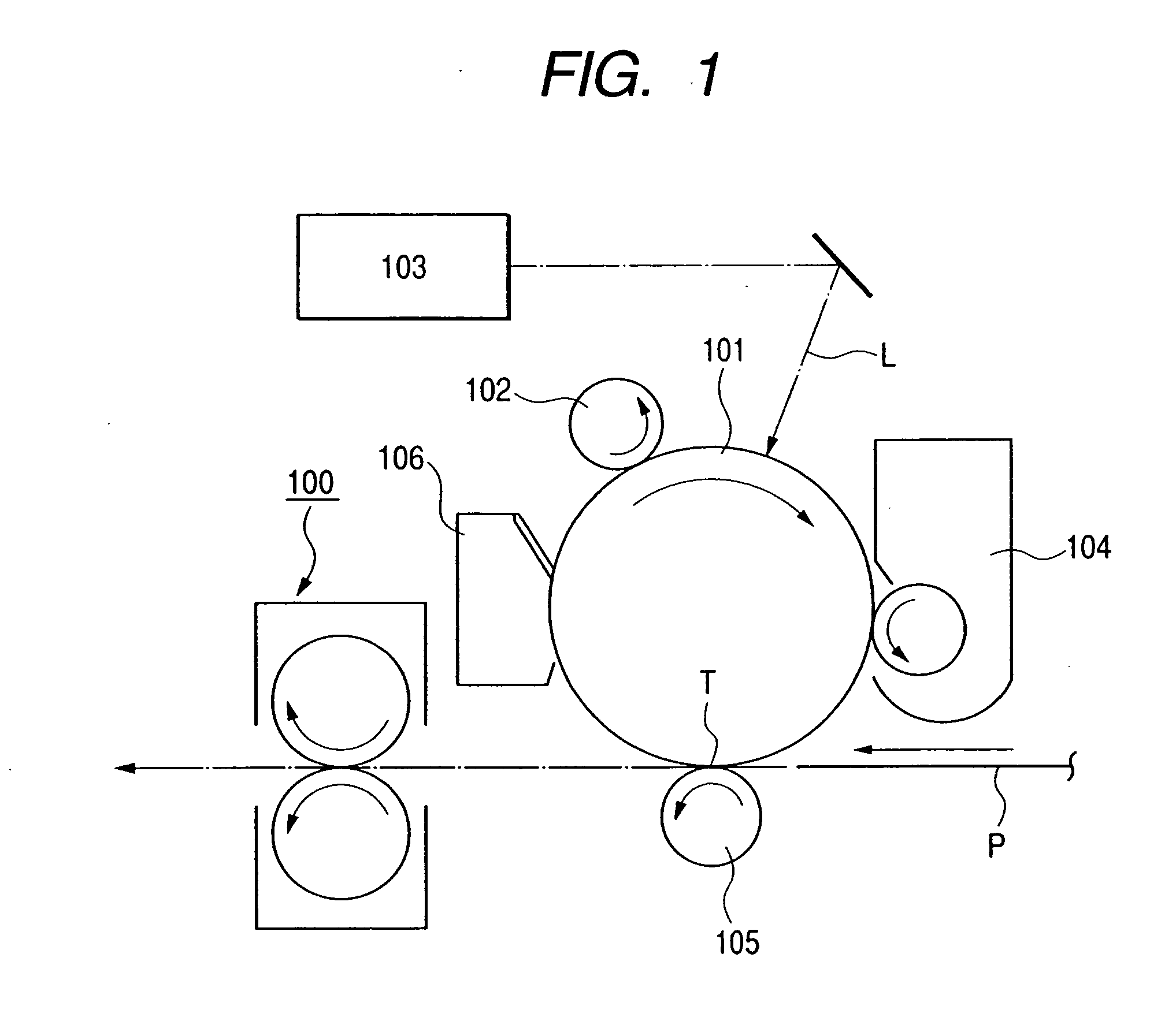
[0034] A fixing apparatus used in an image forming apparatus will hereinafter be described as an example of the heating apparatus of the present invention. FIG. 1 is a model view schematically showing the construction of an image forming apparatus in the present embodiment. The image forming apparatus of the present embodiment is a laser printer utilizing a transfer type electrophotographic process.

[0035] The reference numeral 101 designates a rotary drum-shaped electrophotographic photosensitive member (hereinafter referred to as the photosensitive drum) as an image bearing member which is rotatively driven at a predetermined peripheral speed in the clockwise direction of arrow.

[0036] The reference numeral 102 denotes a charging roller as charging means which uniformly charges the outer peripheral surface of the rotating photosensitive drum 101 to a predetermined polarity and predetermined potential.

[0037] The reference numeral 103 desi...

second embodiment

[0096] Biasing and sliding means for the holder 3 and the magnetic flux shield member 6 which is a second embodiment will now be described with reference to FIGS. 10 and 11.

[0097] In FIG. 10, a magnetic flux shield member rib 6i is provided on the inner surface of a cylinder portion corresponding to the shield portion 6d (6e) of the magnetic flux shield member 6, along the circumferential direction thereof. This magnetic flux shield member rib 6i is constituted by being biased toward and supported on the cylinder portion of the holder 3 by a resilient member, not shown. Accordingly, the holder 3 and the magnetic flux shield member rib 6i are supported so as to contact with each other and therefore, it become possible for the magnetic flux shield member 6 to suppress the vibration sound thereof.

[0098] Further, as compared with the rotating means for the magnetic flux shield member which is not provided with the above-described rib 6i, the area of contact with the holder is decrease...


PUM


Abstract

A heating apparatus of an electromagnetic inductive heat generating type using magnetic flux shield means, having a coil for generating a magnetic flux, a roller member for generating heat by the magnetic flux from the coil, and heating a material to be heated, and a magnetic flux shield member for shielding the magnetic flux from the coil to the roller member to thereby vary the generated heat distribution of the roller member, wherein provision is made of guide means provided in non-contact with the roller member for guiding the movement of the magnetic flux shield member to a predetermined magnetic flux suppressing position, thereby realizing an improvement in the faulty operation of the magnetic flux shield member.

Description

[0001] This application is a divisional of U.S. patent application Ser. No. 10 / 862,447, filed Jun. 8, 2004.BACKGROUND OF THE INVENTION [0002] 1. Field of the Invention [0003] This invention relates, for example, in an image forming apparatus, to a heating apparatus suitable for use as an image heating apparatus for fixing an unfixed image formed and borne on a recording material, and particularly to a heating apparatus of an electromagnetic (magnetic) induction heating type. [0004] 2. Description of Related Art [0005] Description will hereinafter be made with an image heating and fixing apparatus in an image forming apparatus such as an electrophotographic copying machine, a printer or a facsimile apparatus taken as an example. [0006] The image heating and fixing apparatus in the image forming apparatus is an apparatus in which an unfixed toner image formed on the surface of a recording material by a direct process or an indirect (transfer) process is heated and fixed as a permanent...

Claims


Application Information

Patent Timeline
Patent Type & Authority Applications(United States)
IPC IPC(8): G03G15/20H05B6/14H05B6/40
CPCG03G15/2053
Inventor KATO, DAIJIROWATANABE, KOKI
Owner CANON KK
Why Eureka
Try Eureka