

Solar driven concentration cell
a concentration cell, solar energy technology, applied in the direction of indirect fuel cells, non-aqueous electrolyte cells, cell components, etc., can solve the problems of not being adapted, not being constant, and not producing the voltage produced by the concentration cell
- Summary
- Abstract
- Description
- Claims
- Application Information
AI Technical Summary
Benefits of technology
Problems solved by technology
Method used
Image

Examples
example 1
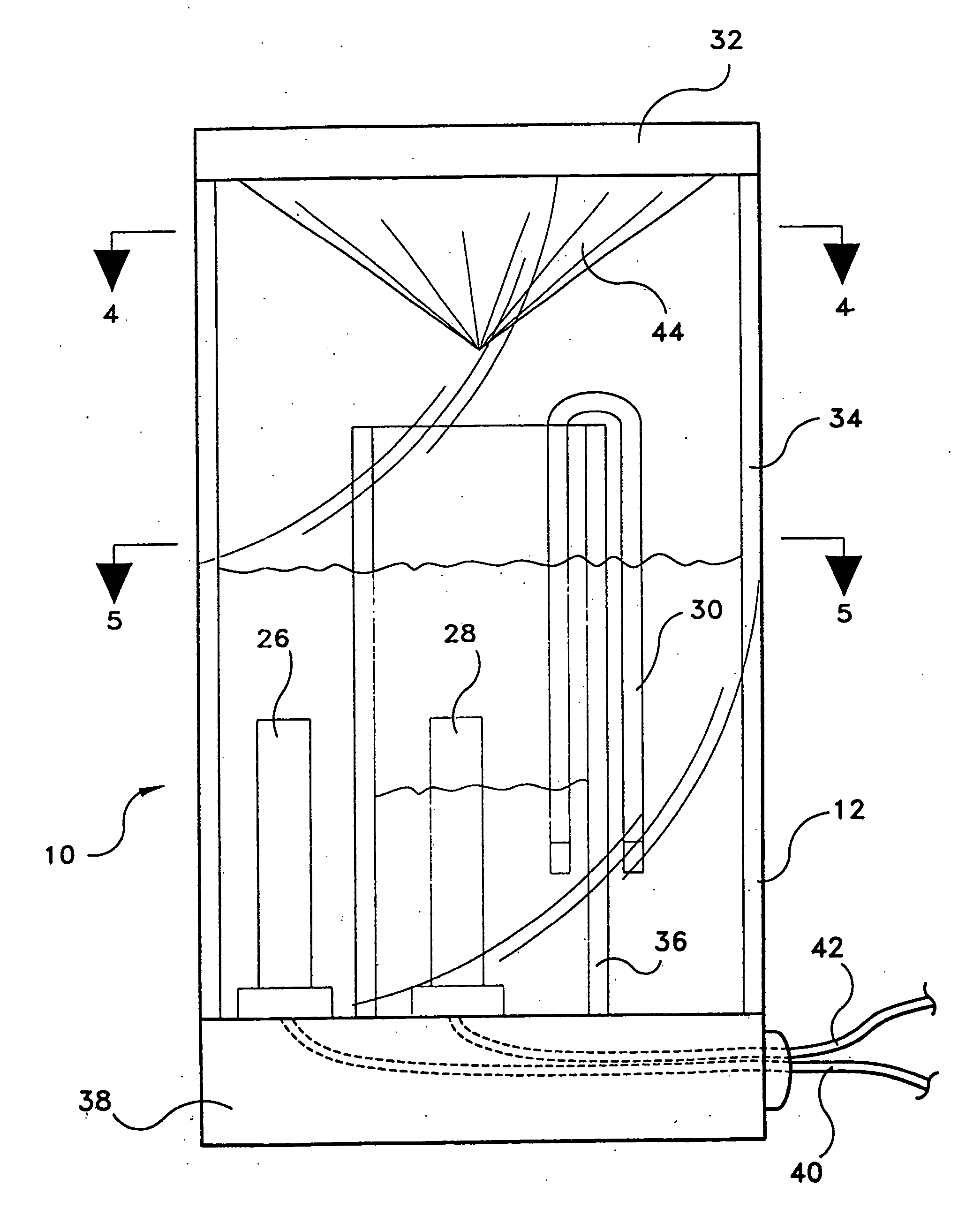
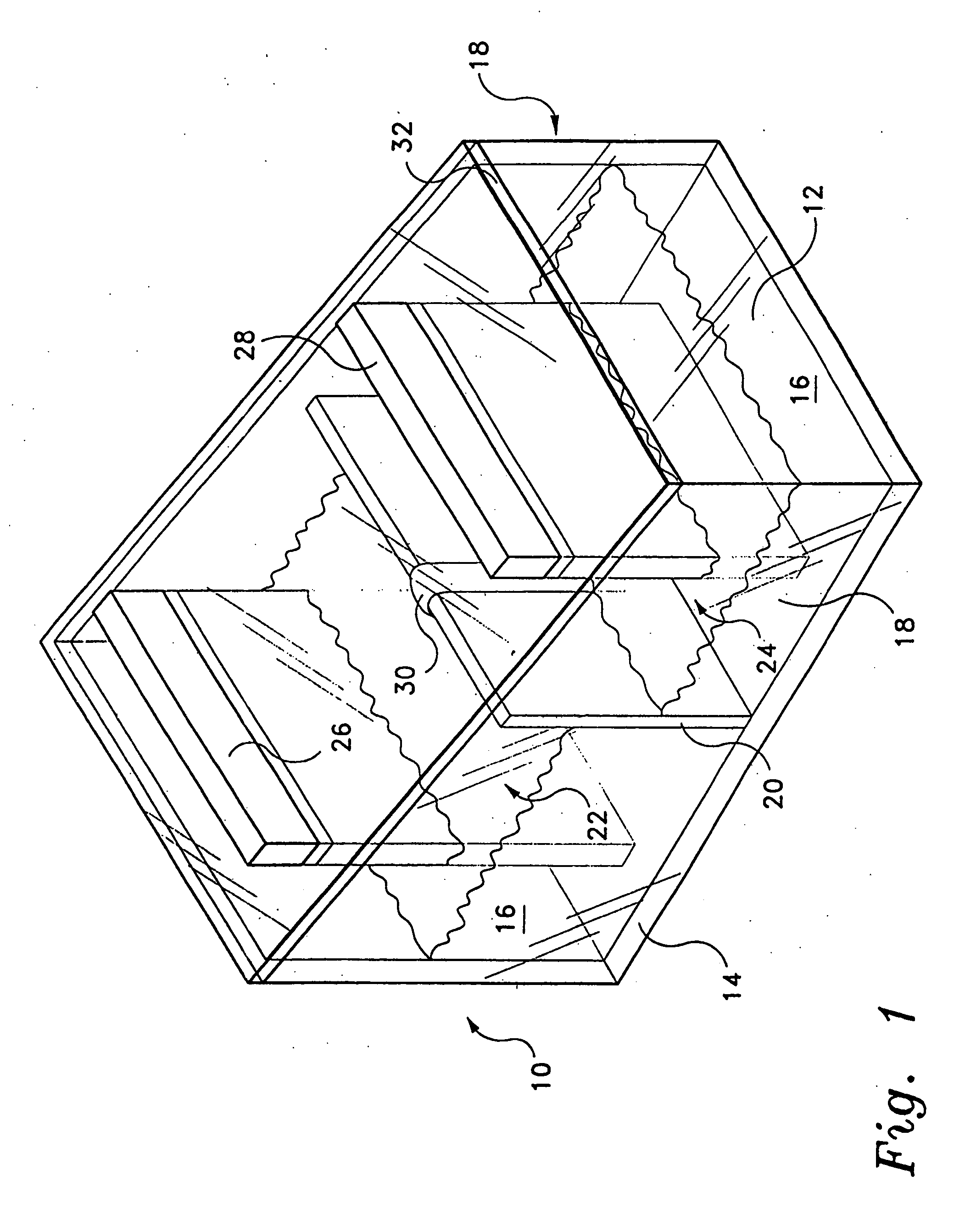
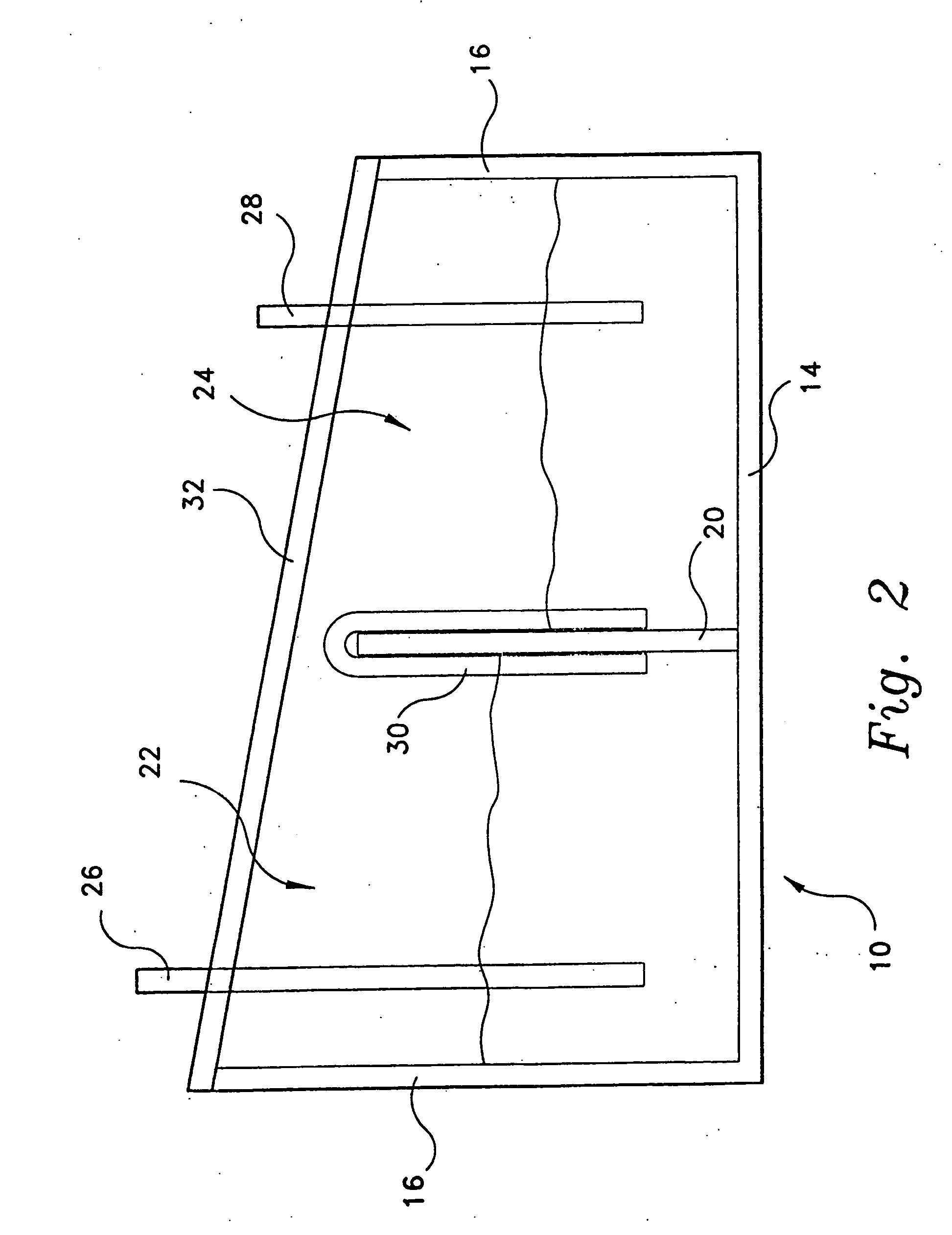
[0046] A fully sealed concentration cell was constructed of transparent polycarbonate plastic material. The cell was divided to form two half-cells. A slanted roof, having the higher side covering the cathode half-cell and the lower side covering the anode half-cell, was constructed of transparent polycarbonate plastic material. Into each half-cell was placed a copper electrode and an aqueous solution of copper (II) chloride dihydrate, with the electrode partially submerged in the aqueous solution. The cathode half-cell contained a 1.0 M aqueous solution of copper (II) chloride dihydrate; and the anode half-cell contained a 0.0001 M aqueous solution of copper (II) chloride dihydrate. The two half-cells were connected with a salt bridge, in this example the salt bridge being a paper towel wetted with the aqueous solution of copper (II) chloride dihydrate
[0047] The internal resistance of the concentration cell was 60,000 ohms, and the initial voltage was 0.15 Volts. The cell was plac...
example 2
[0048] Two fully sealed concentration cells were constructed of transparent polycarbonate plastic material. The structural geometry of the cells was similar to that of the cell in Example 1, i.e., two half-cells with a slanted roof. The salt bridge for each cell was a U-shaped glass tube packed with unwoven cotton which was soaked in an aqueous solution of sodium chloride. The anode half-cell contained a copper electrode partially submerged in an aqueous solution of copper (II) sulfate (0.001 M). The cathode half-cell contained a copper electrode partially submerged in an aqueous solution of copper (II) sulfate (0.003 M). Each solution contained about 10 mL of vinegar to lower the pH and thus prevent precipitation of copper hydroxide.
[0049] One of the two concentration cells was painted black on the sides of the cathode compartment. Both cells were then placed in sunlight. Change in voltage over time was then measured for each cell. The following chart records the results.
Time (h...
example 3
[0051] A fully sealed concentration cell was constructed of transparent polycarbonate material. The cell was divided to form two half-cells. A slanted roof, having the higher side covering the cathode half-cell and the lower side covering the anode half-cell, was constructed of transparent polycarbonate plastic material. Into each half-cell was placed a copper electrode and an aqueous solution of copper (II) sulfate. The cathode half-cell contained a 1.0 M aqueous solution of copper (II) sulfate; and the anode half-cell contained a 0.0001 M aqueous solution of copper (II) chloride dihydrate. The two half-cells were connected with a salt bridge, the salt bridge being a U-shaped glass tube filled with unwoven cotton which had previously been soaked in an aqueous sodium chloride solution for about twenty minutes.
[0052] The initial voltage of the concentration cells was 22 mV. After 48 hours in a dimly lit and cool basement room (20° C.), the voltage was measured at 20 mV.
[0053] The c...
PUM
 Abstract
Description
Claims
Application Information