

Concentration cell
A concentration battery and electrode technology, applied in the field of high-efficiency and continuous power generation ion concentration battery, can solve the problem of low power generation efficiency, consistent pressure on both sides of electrode isolation, and difficulty in forming a solution interface where high-concentration solution and low-concentration solution are in contact, etc. problem, to achieve the effect of simple structure
- Summary
- Abstract
- Description
- Claims
- Application Information
AI Technical Summary
Problems solved by technology
Method used
Image

Examples
no. 1 approach
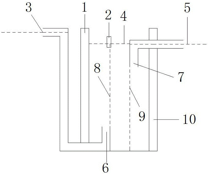
[0023] The first embodiment, such as figure 1 A concentration difference battery includes an electrode 1, an electrode 10, a solution outlet 2, a low-concentration solution inlet 6, and a high-concentration solution inlet 7. One of the electrode 1 and the electrode 10 is a positive electrode and the other is a negative electrode. Between the electrode 1 and the electrode 10 The solution pool is equipped with a high / low concentration solution, and the low concentration solution enters the solution pool from the low concentration solution inlet 6. Since the low concentration solution rises to form a low concentration solution flow layer 8, the high concentration solution enters from the high concentration solution inlet 7 In the solution pool, the high-concentration solution descends to form a high-concentration solution flow layer 9, the high-concentration solution flow layer and the low-concentration solution flow layer are in contact with each other and do not intersect each o...
no. 2 approach
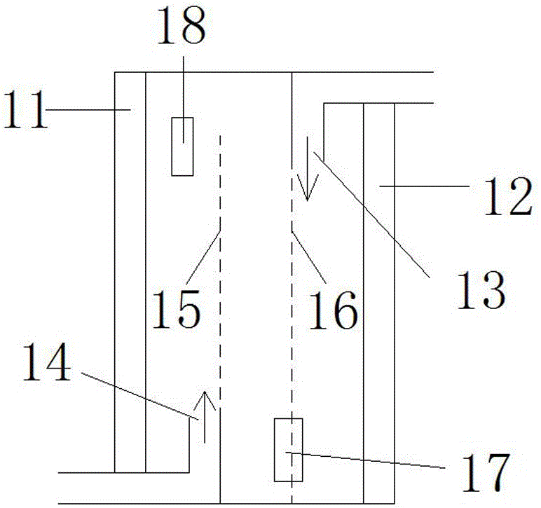
[0024] The second embodiment, such as figure 2A concentration difference battery comprises an electrode 11, an electrode 12, a solution outlet 18, a solution outlet 17, a high-concentration solution inlet 13, and a low-concentration solution inlet 14, and the low-concentration solution enters between the electrode 11 and the electrode 12 from the low-concentration solution inlet 14 The solution pool of the solution pool forms the low-concentration solution flow layer 15, and the high-concentration solution enters the described solution pool from the high-concentration solution inlet 13, and forms a high-concentration solution flow layer 16, and the low-concentration solution flow layer 15 and the high-concentration solution flow layer 16 are connected to each other The contacts do not intersect, and the formed potential is output by the electrodes 11 and 12, one of which is a positive electrode and the other is a negative electrode. The solution after the high-concentration so...
no. 3 approach
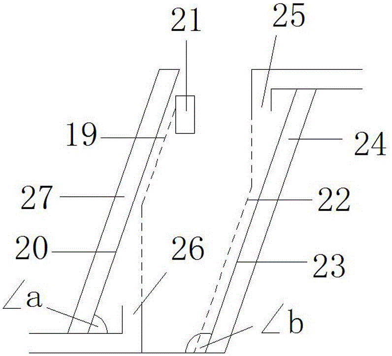
[0025] The third embodiment, such as image 3 A kind of concentration difference battery comprises electrode 27, electrode 24, solution outlet 21, low-concentration solution inlet 26, high-concentration solution inlet 25, and low-concentration solution enters the solution pool between electrode 27 and electrode 24 from low-concentration solution inlet 26, forms low Concentration solution flow layer 19, high concentration solution enters described solution pool from high concentration solution inlet 25, forms high concentration solution flow layer 22, and the solution formed by interdiffusion of low concentration solution and high concentration solution is discharged from solution outlet 21, electrode 27 The angle ∠a formed between the electrode contact surface 20 in contact with the low-concentration solution and the horizontal plane, 90 degrees ≥ ∠a>0 degree, the angle ∠b formed between the electrode contact surface 23 and the horizontal plane formed by the high-concentration ...
PUM
| Property | Measurement | Unit |
|---|---|---|
| Angle | aaaaa | aaaaa |
| Angle | aaaaa | aaaaa |
Abstract
Description
Claims
Application Information