
Audio coding and decoding apparatuses and methods, and recording mediums storing the methods

a technology of applied in the field of audio coding and decoding apparatus, and recording medium, can solve the problems of waveform distortion and discontinuity occurring at the frame boundary, and the disadvantageous increase or decrease linearly of synthesis excitation signal, so as to achieve the effect of easy application and scalability

Inactive Publication Date: 2006-09-14
SAMSUNG ELECTRONICS CO LTD
View PDF8 Cites 15 Cited by
  • Summary
  • Abstract
  • Description
  • Claims
  • Application Information

AI Technical Summary

Benefits of technology

[0013] An aspect of the present invention also provides audio coding and decoding apparatuses and methods in which scalability can be easily applied, and recording mediums on which the methods are recorded.

Problems solved by technology

When the pitch halving prediction or the pitch doubling prediction is performed, waveform distortion and discontinuity occur at a frame boundary due to a severe amount of variation of pitch lag.
In addition, since an overlap-addition method through a triangular window is used in harmonic synthesis, when a signal in an audio signal section including harmonics in a transition section increases or decreases instantaneously, a synthesis excitation signal may disadvantageously increase or decrease linearly due to the effect of the triangular window.

Method used


Image

  • Audio coding and decoding apparatuses and methods, and recording mediums storing the methods
  • Audio coding and decoding apparatuses and methods, and recording mediums storing the methods
  • Audio coding and decoding apparatuses and methods, and recording mediums storing the methods

Examples


Embodiment Construction

[0030] Reference will now be made in detail to embodiments of the present invention, examples of which are illustrated in the accompanying drawings, wherein like reference numerals refer to the like elements throughout. The embodiments are described below in order to explain the present invention by referring to the figures.

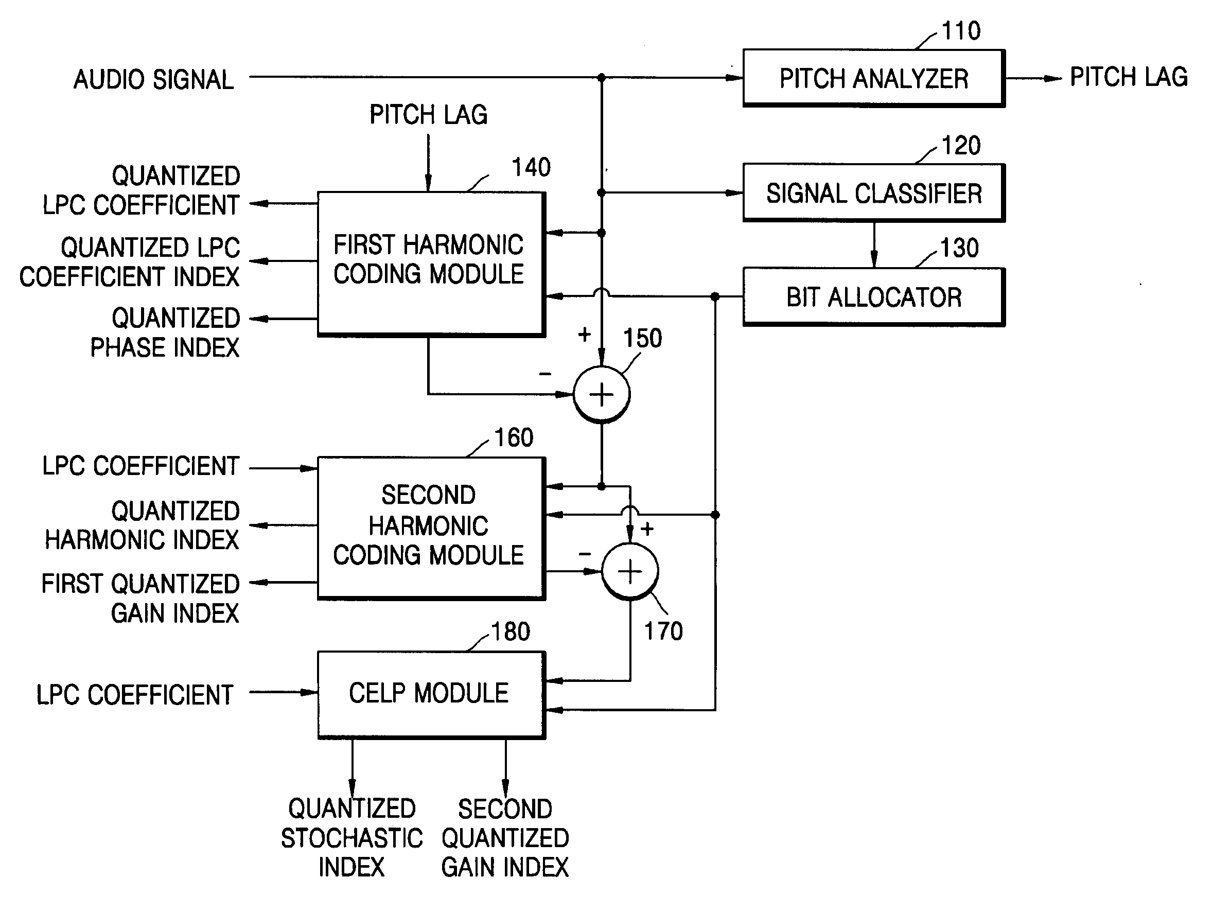
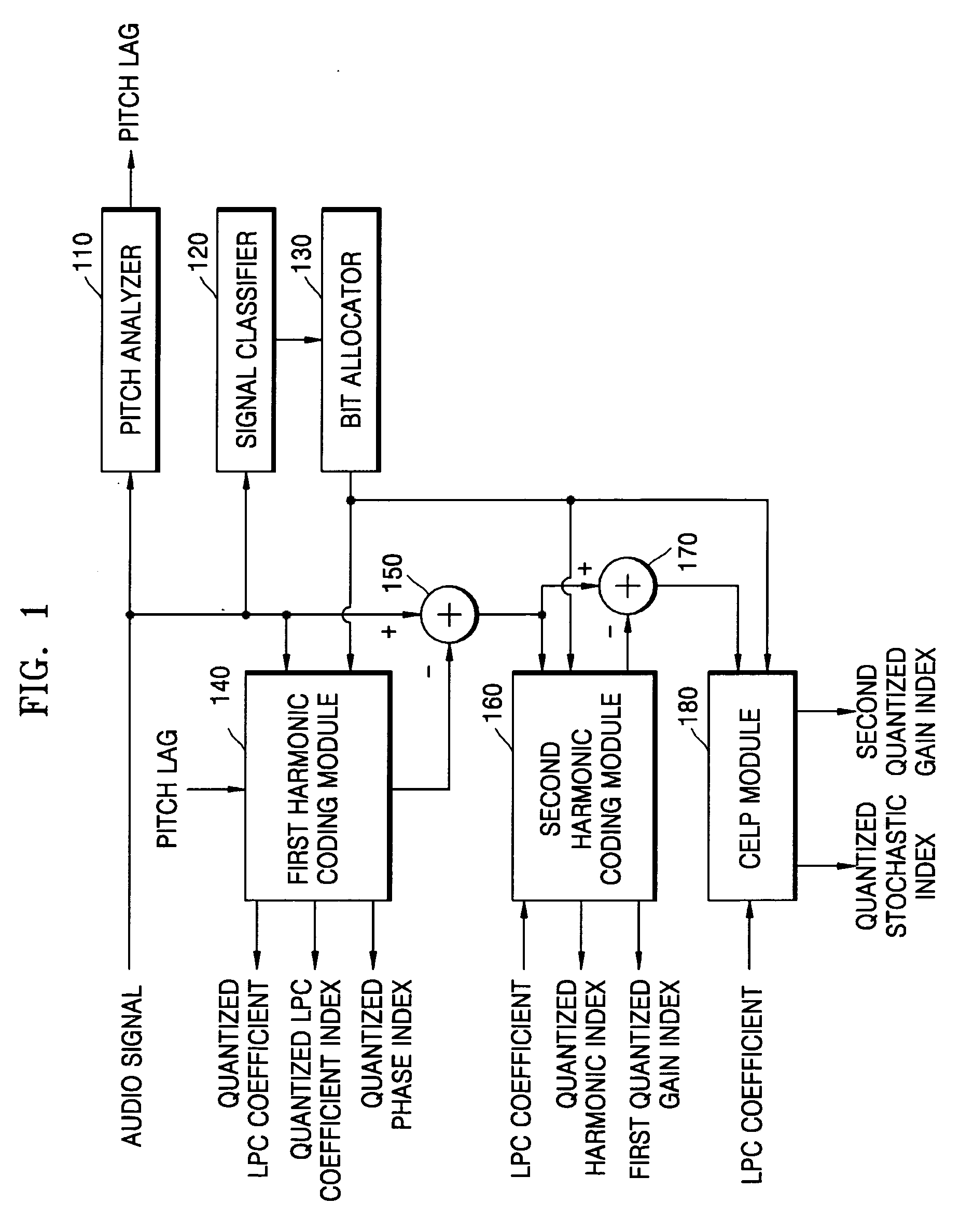
[0031]FIG. 1 is a functional block diagram of an audio coding apparatus according to an embodiment of the present invention. Referring to FIG. 1, the audio coding apparatus includes a pitch analyzer 110, a signal classifier 120, a bit allocator 130, a first harmonic coding module 140, a first detector 150, a second harmonic coding module 160, a second detector 170, and a code excited linear prediction (CELP) module 180.

[0032] The pitch analyzer 110 analyzes the pitch of an input audio signal and detects a pitch lag tp. The pitch lag tp is obtained using a normalized auto-correlation function shown in Equation 1 R⁡(i)=∑n=0LI-1⁢s⁡(n)⁢s⁡(n-i)∑n=0LI-1⁢s2⁡(n-i),i=LM...


PUM


Abstract

Audio coding and decoding apparatuses and methods that can optimize the quality of an audio signal including harmonics, and recording mediums storing the methods. An audio coding apparatus includes: a first harmonic coding module performing first harmonic coding on an input audio signal using a pitch lag of the input audio signal and producing a quantized linear prediction coding coefficient; a first detector detecting a first difference audio signal from a difference between an audio signal output from the first harmonic coding module and the input audio signal; a second harmonic coding module performing harmonic coding on the first difference audio signal using the quantized linear prediction coding coefficient and a previous harmonic coding result; a second detector detecting a second difference audio signal obtained from a difference between an audio signal output from the second harmonic coding module and the first difference audio signal; and a code excited linear prediction (CELP) module CELP coding the second difference audio signal using the quantized linear prediction coding coefficient obtained from the first harmonic coding module.

Description

CROSS-REFERENCE TO RELATED APPLICATION [0001] This application claims the benefit of Korean Patent Application No. 10-2005-0020136, filed on Mar. 10, 2005, in the Korean Intellectual Property Office, the disclosure of which incorporated herein by reference. BACKGROUND OF THE INVENTION [0002] 1. Field of the Invention [0003] The present invention relates to audio coding and decoding apparatuses and methods, and recording mediums on which the methods are recorded, and more particularly, to audio coding and decoding apparatuses and methods in which the quality of an audio signal including harmonics can be optimized, and recording mediums on which the methods are recorded. [0004] 2. Description of Related Art [0005] As the range of applications of audio coders has increased, the demand for low transmission rate coders has also increased. As such, a code excited linear prediction (CELP) coder is being used for transmission rates equal to or greater than 4 kbps, and a harmonic-CELP coder ...

Claims


Application Information

Patent Timeline
IPC IPC(8): G10L11/04G10L25/90
CPCG10L19/06G10L19/09G10L19/093G10L19/24
Inventor SUNG, HOSANGTAORI, RAKESHLEE, KANGEUN
Owner SAMSUNG ELECTRONICS CO LTD
Learn More