Video conferencing system, conference terminal and image server

a video conferencing and conference terminal technology, applied in the field of video conferencing techniques, can solve the problems of increasing the required bandwidth and the cost of the system, unable to confirm the state of a key person (such as a chairperson) of the conference, and the difficulty of a participant of the conference to confirm the state of the other participants, so as to reduce the required bandwidth, suppress the required band, and facilitate the effect of confirming the state of a key person or the like of a conferen

Inactive Publication Date: 2006-09-14
HITACHI LTD
View PDF6 Cites 52 Cited by
  • Summary
  • Abstract
  • Description
  • Claims
  • Application Information

AI Technical Summary

Benefits of technology

[0041] According to the present invention, a conference terminal displays image data of each user located forward in relation to the location and direction of the user of that conference terminal. The location and direction of the user of the conference terminal in question are designated by that user. As a result, a required bandwidth can be reduced in comparison with a case where image data of all the users are displayed in a conference terminal. Further, when

Problems solved by technology

The larger the number of participants of a conference becomes, the larger the required bandwidth becomes and the larger the cost of the system becomes.
However, only speaking persons are displayed,

Method used


Image

  • Video conferencing system, conference terminal and image server
  • Video conferencing system, conference terminal and image server
  • Video conferencing system, conference terminal and image server

Examples


first embodiment

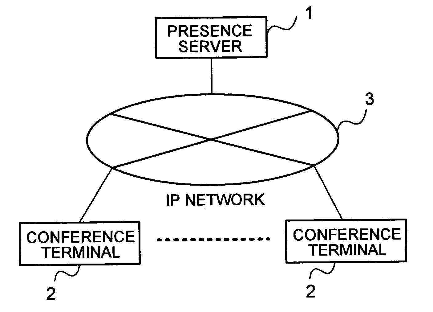
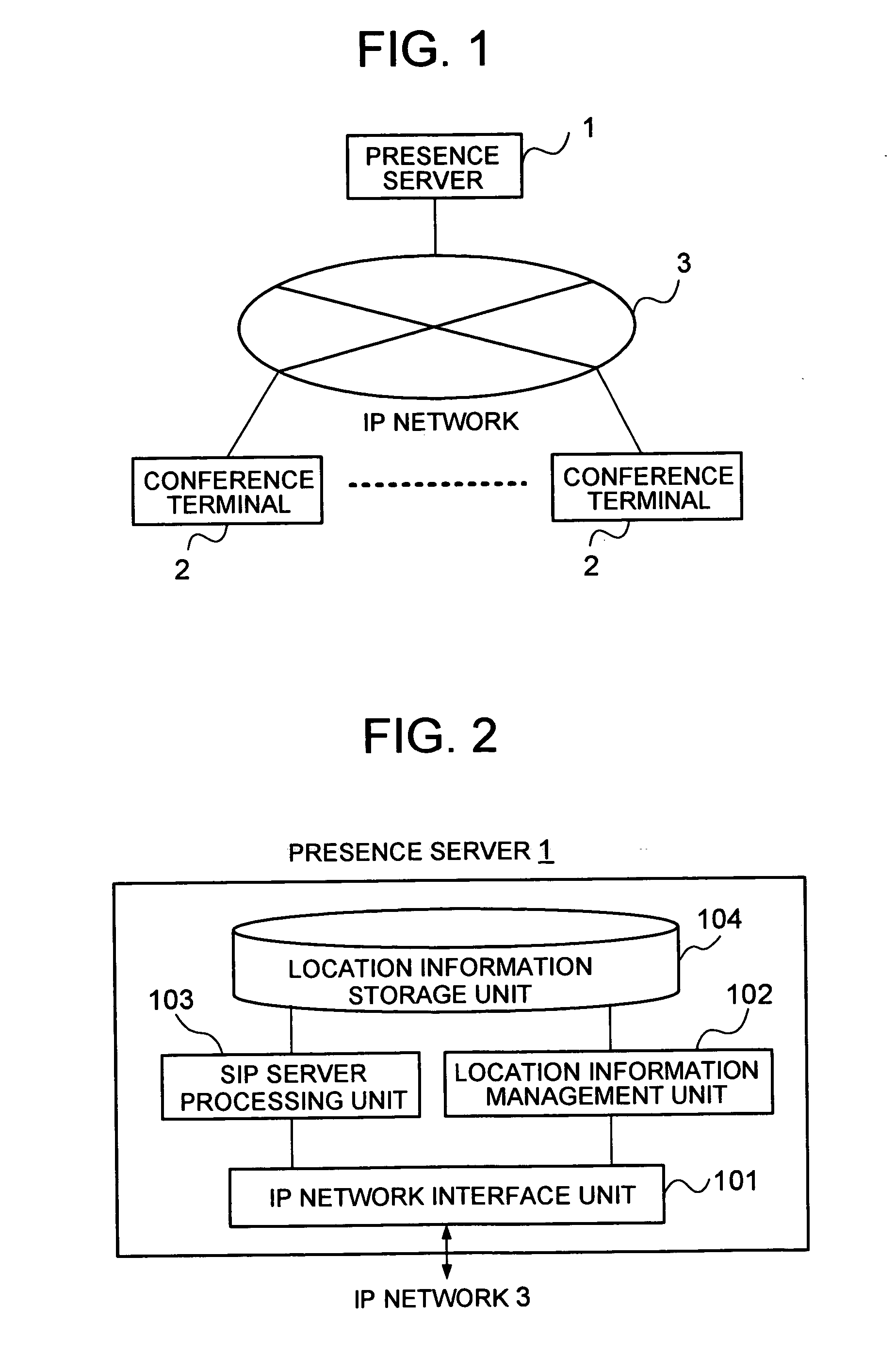
[0065]FIG. 1 is a schematic block diagram showing a video conferencing system of a first embodiment of the present invention. As shown in the figure, the video conferencing system of the present embodiment comprises a presence server 1 and a plurality of conference terminals 2, with these component apparatuses 1 and 2 being connected with one another through an IP (Internet Protocol) network 3.

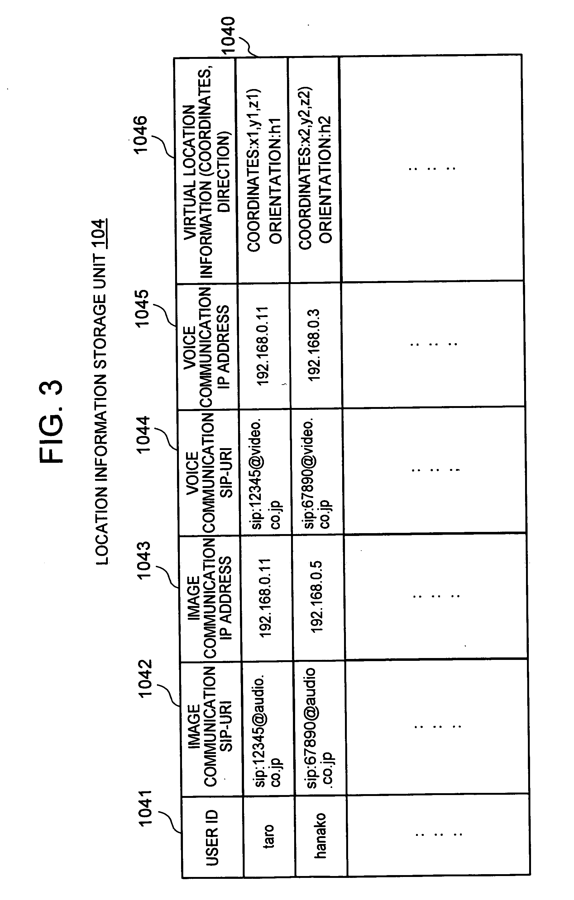
[0066] The presence server 1 manages location information of a user of each conference terminal 2 in a virtual space. Here, the virtual space is a virtually-generated space for the users of the conference terminals 2 to have a conference. The virtual space has properties such as: a size of the space; a height of a ceiling; reflectances, colors and textures of walls and the ceiling; reverberation properties; sound absorptance owing to air in the space; and the like.

[0067]FIG. 2 is a schematic block diagram showing the presence server 1.

[0068] As shown in the figure, the presence server 1 com...

second embodiment

[0136]FIG. 17 is a schematic block diagram showing a video conferencing system of a second embodiment of the present invention. As shown in the figure, the video conferencing system of the present embodiment comprises a presence server 1′, an image server 4, a voice server 5, and a plurality of conference terminals 2, with these component apparatuses being connected with one another through an IP network 3.

[0137] The presence server 1′ receives virtual location information of a user of each conference terminal 2′ from that conference terminal 2′ and manages the received virtual location information. Further, in response to a location information sending request from the image server 4 or the voice server 5, the presence server 1′ sends the virtual location information of the user of each conference terminal 2′ to the image server 4 or the voice server 5. Here, the presence server 1′ of the present embodiment is different from the presence server 1 shown in FIG. 2 of the first embod...


PUM


Abstract

In a video conferencing system, required bandwidth is suppressed to a lower level and a key person or the like of a conference can be confirmed easily. A presence server 1 manages location information in a virtual space for a user of each conference terminal 2. Each conference terminal 2 sends image data of its own user to another conference terminal 2 in response to a request of that conference terminal 2. Further, each conference terminal 2 receives location information of its own user in the virtual space, sends the received location information to the presence server 1, and receives location information of the other users from the presence server 1. Then, based on the location information of its own user and the location information of the other users, the conference terminal 2 detects forward users located forward from its own user, and receives image data from the conference terminal 2 of each of the forward users.

Description

CLAIM OF PRIORITY [0001] The present invention claims priority from Japanese Patent Application No. JP2005-068917 filed Mar. 11, 2005, the content of which is hereby incorporated by reference into this application. BACKGROUND OF THE INVENTION [0002] The present invention relates to a video conferencing technique in which a conference terminal can output stereophonically-processed voices together with images of participants of a conference. [0003] Patent Document 1 (U.S. Pat. No. 4,400,724) discloses an all-participants-displaying-type video conferencing system. In this all-participants-displaying-type video conferencing system, a video conference terminal of each participant is provided with display units as many as the number of the participants of a conference, to display respective images of the participants of the conference. Thus, the images of all the participants of the conference are always displayed. [0004] Further, Patent Document 2 (U.S. Pat. No. 6,330,022) discloses a fl...

Claims


Application Information

Patent Timeline
IPC IPC(8): G06F15/16
CPCH04L29/06027H04L29/12094H04L29/1216H04L61/1529H04L61/157H04L65/1069H04L65/4038H04L61/4535H04L61/4557H04L65/1101
Inventor KANADA, YASUSI
Owner HITACHI LTD
Why Eureka
Try Eureka