Electronic-component holding apparatus, electronic-component mounting system, and electronic-component mounting method

a technology of electronic components and holding devices, which is applied in metal working devices, printed circuit manufacture, manufacturing tools, etc., can solve the problems of cumbersome attachment of the nozzle head to the nozzle holding member, and lowering the efficiency of mounting electronic components

Active Publication Date: 2006-09-21
FUJI MASCH MFG CO LTD
View PDF12 Cites 31 Cited by
  • Summary
  • Abstract
  • Description
  • Claims
  • Application Information

AI Technical Summary

Benefits of technology

[0008] It is therefore an object of the present invention to provide an electronic-component holding apparatus, an electronic-component mounting system, and an electronic-component mounting method each of which enjoys an advantage that a nozzle head is easily attached to, and detached from, a head holding member.

Problems solved by technology

However, it is cumbersome to attach the nozzle head to the nozzle holding member while operating the head clamping device.
That is, it is time-consuming to attach and detach, while operating the head clamping device, the nozzle head to and from the nozzle holding member, which may lead to lowering an efficiency of mounting of electronic components.

Method used


Image

  • Electronic-component holding apparatus, electronic-component mounting system, and electronic-component mounting method
  • Electronic-component holding apparatus, electronic-component mounting system, and electronic-component mounting method
  • Electronic-component holding apparatus, electronic-component mounting system, and electronic-component mounting method

Examples


Embodiment Construction

[0117] Hereinafter, preferred embodiments of the present invention will be described in detail by reference to the drawings.

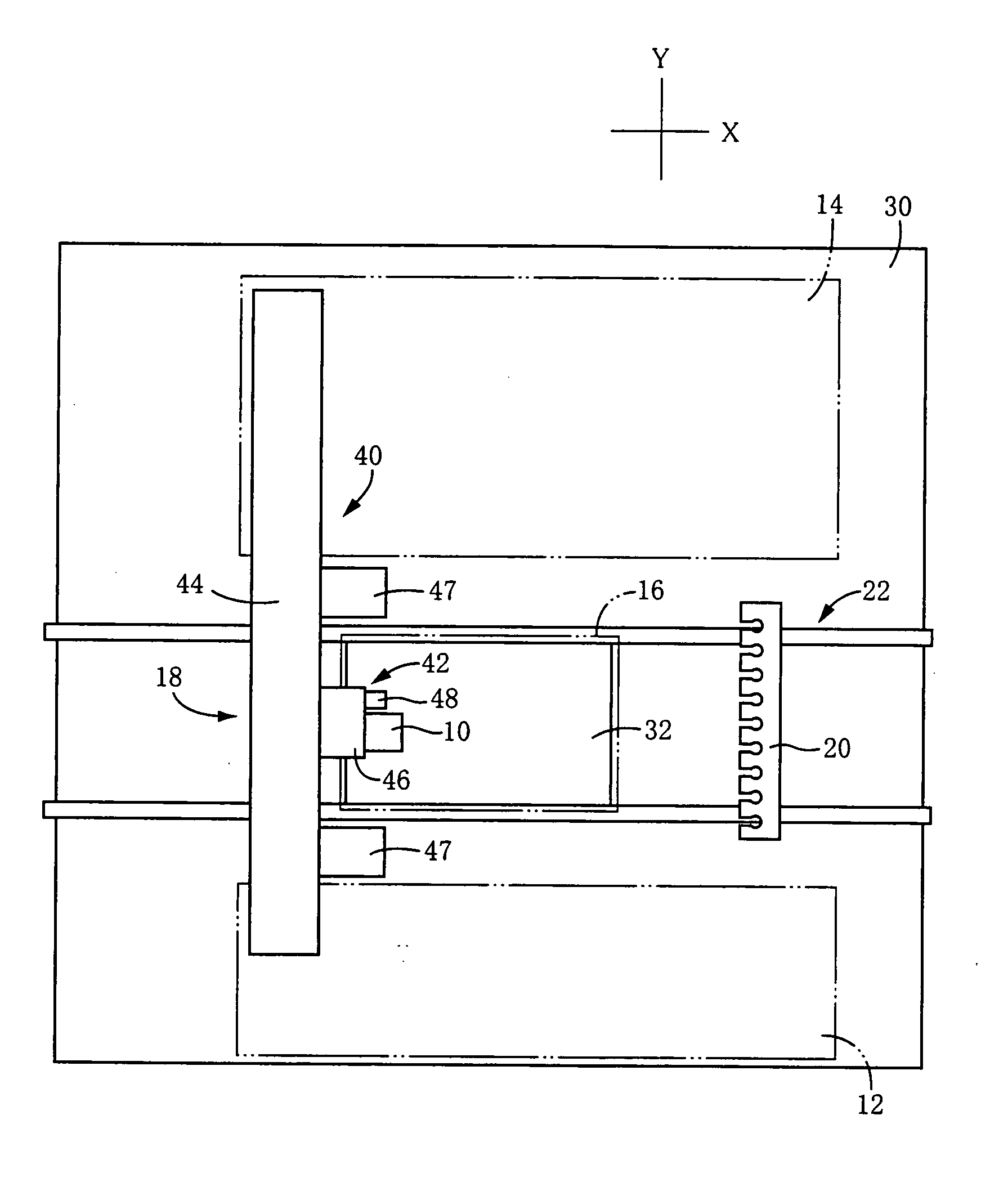
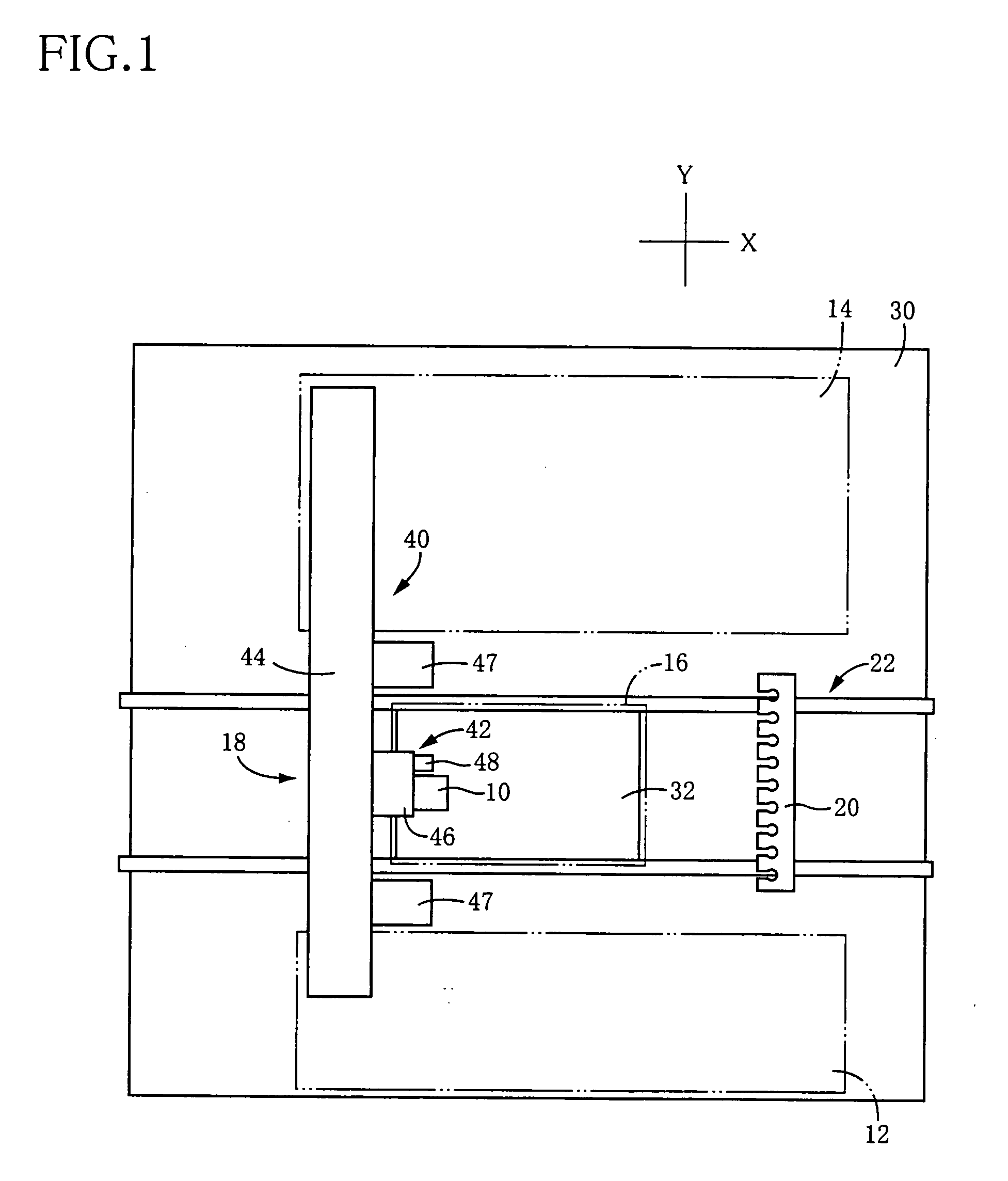
[0118]FIG. 1 shows an electronic-component mounting system to which the present invention is applied. The electronic-component mounting system includes an electronic-component holding apparatus 10; a feeder-type electronic-component supplying device 12 and a tray-type electronic-component supplying device 14 each as a sort of electronic-component supplying device; a circuit-substrate holding device 16; an electronic-component-holding-apparatus moving device 18; a head storage device 20; a circuit-substrate conveying device 22; and a control device 24 (FIG. 20).

[0119] The substrate conveying device 22 is provided on a bed 30 as a support member of the present mounting system, and includes, e.g., a belt conveyor that conveys a circuit substrate 32 in one horizontal direction so as to carry in, and out, the circuit substrate 32 to, and from, the substrate holdin...


PUM

PropertyMeasurementUnit
pressureaaaaaaaaaa
thicknessaaaaaaaaaa
suctionaaaaaaaaaa

Abstract

An electronic-component holding apparatus, an electronic-component mounting system, and an electronic-component mounting method each of which assures that a nozzle head holding at least one suction nozzle is easily attached to, and detached from, a head holding member, are provided. A suction surface 130 of a head holding member 52 is held in close contact with a to-be-sucked surface 200 of a revolver head 56, so as to define a head-related negative-pressure chamber 204 that holds the revolver head 56 by utilizing suction based on a negative pressure. The revolver head 56 is rotated, and moved upward and downward, with the head holding member 52. The revolver head 56 has twelve suction nozzles 212 and twelve valve devices 264. Owing to the upward and downward movements of the head holding member 52, a lever drive member 510 engages a pivotable lever 224, a first spool valve 280, and a second spool valve 310, so as to move mechanically a corresponding suction nozzle 212 upward and downward and switch mechanically a corresponding valve device 264 to an arbitrary one of its negative-pressure supply state and its positive-pressure supply state, so that the corresponding suction nozzle 212 holds and mounts an electronic component.

Description

[0001] The present application is based on Japanese Patent Application No. 2005-075397 filed on Mar. 16, 2005, the contents of which are incorporated herein by reference. BACKGROUND OF THE INVENTION [0002] 1. Field of the Invention [0003] The present invention relates to an electronic-component holding apparatus, an electronic-component mounting system, and an electronic-component mounting method, and particularly to an electronic-component holding apparatus including a plural-nozzle head that holds a plurality of suction nozzles adapted to hold respective electronic components, and a head holding member that holds the plural-nozzle head such that the plural-nozzle head is detachable from the head holding member; an electronic-component mounting system including the electronic-component holding apparatus; and an electronic-component mounting method using the electronic-component holding apparatus. [0004] 2. Discussion of Related Art [0005] An example of the above-indicated electroni...

Claims


Application Information

Patent Timeline
Patent Type & Authority Applications(United States)
IPC IPC(8): H05K3/30B23P19/00
CPCH05K13/0408H05K13/0452Y10T29/53178Y10T29/4913Y10T29/53191Y10T29/53174H05K13/0404H05K13/0409H05K13/041
Inventor KAWADA, TOSUKE
Owner FUJI MASCH MFG CO LTD
Why Eureka
Try Eureka