Optical apparatus with dust reduction capability
a technology of optical apparatus and dust reduction glasses, which is applied in the field of optical apparatuses with dust reduction glasses, can solve the problem of no dust reduction measures for optical apparatuses provided with dust reduction glasses
- Summary
- Abstract
- Description
- Claims
- Application Information
AI Technical Summary
Benefits of technology
Problems solved by technology
Method used
Image
Examples
first embodiment
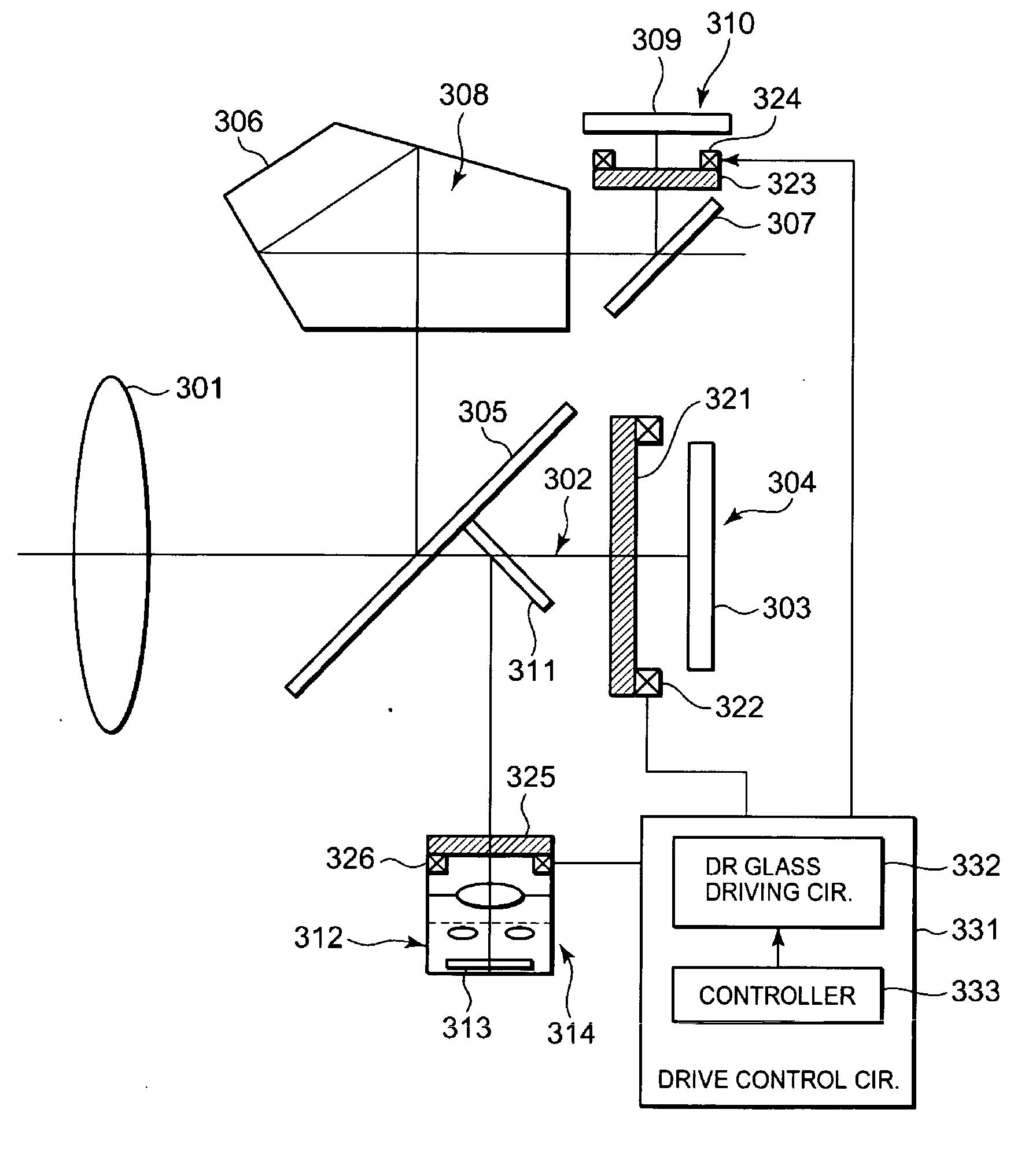
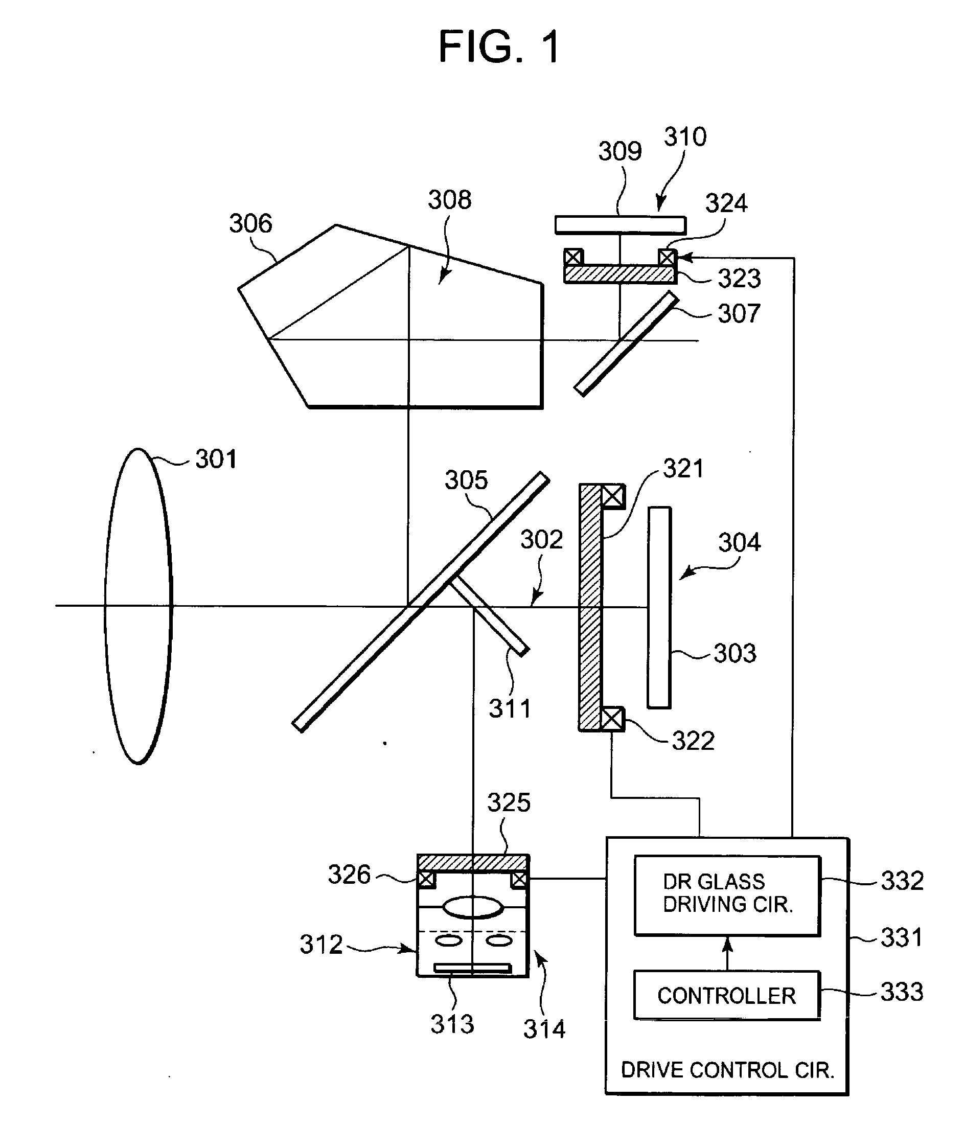
[0065]FIG. 1 is a schematic diagram of a digital camera system as an optical apparatus with dust reduction capability according to a first embodiment of the present invention. FIG. 1 shows the structure of the digital camera with consideration given to an actual optical arrangement.
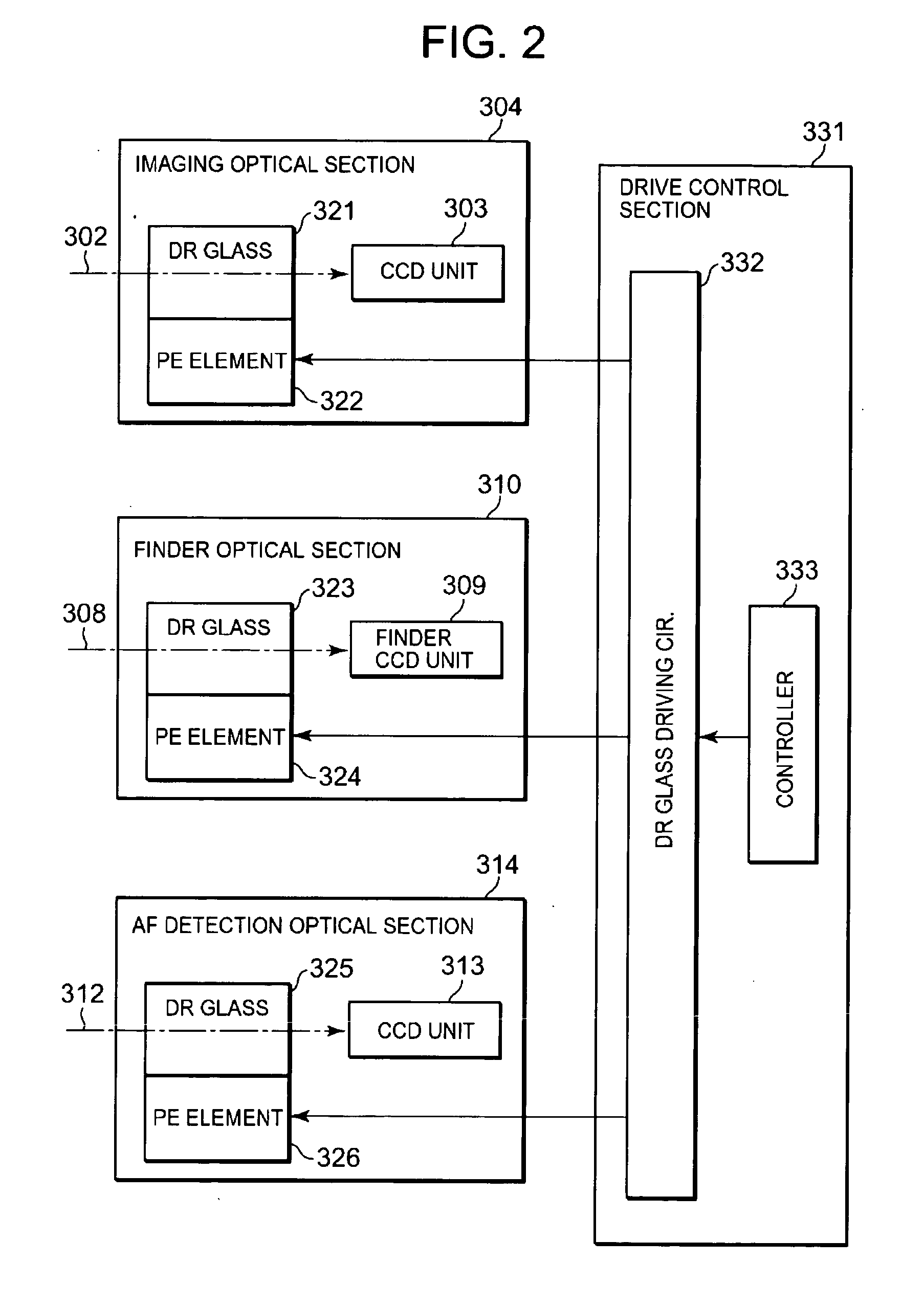
[0066] The optical apparatus with dust reduction capability includes an imaging optical section 304. The imaging optical section 304 has an imaging optical system 302 and a CCD unit 303. The imaging optical system 302 is an image-forming optical system having a taking lens 301 as its main part. The CCD unit 303 is a photoelectric converter, or to be more specific, an imaging photoelectric converter, for receiving an optical subject image formed through the imaging optical system 302 and converting it to an electric signal.
[0067] The optical apparatus with dust reduction capability also includes a finder optical section 310. The finder optical section 310 has a finder optical system 308 and a finder CCD ...
second embodiment
[0150] The following describes a second embodiment of the present invention. In summary, in the second embodiment, the drive control section 331 selectively drives each of the piezoelectric elements 322, 324, and 326 to vibrate each of the dust reduction glasses 321, 323, and 325 in a time-sharing manner. Particularly, the second embodiment assumes a case where each of the dust reduction glasses 321, 323, and 325 has a different resonance frequency as indicated by fc 321, fc 323, or fc 325, respectively. In operation, the drive control section 331 selectively drives each of the piezoelectric elements 322, 324, and 326 to scan a predetermined frequency range including the resonance frequency of each of the dust reduction glasses 321, 323, and 325 so as to vibrate each of the dust reduction glasses 321, 323, and 325 in a time-sharing manner. For example, the driving frequency is so changed that the dust reduction glass 321 will be driven only for a period during which the driving freq...
third embodiment
[0157] The following describes a third embodiment of the present invention. The description of the third embodiment focuses on the point that the vibration exciting element is the piezoelectric element. In summary, each of the piezoelectric elements 322, 324, and 326 is applied with a voltage varying from element to element. In other words, the applied voltage is used as an optimum parameter for each of the piezoelectric elements 322, 324, and 326 to vibrate each of the dust reduction glasses 321, 323, and 325, so that the applied voltage is switched to vibrate each of the dust reduction glass 321, 323, and 325 for dust reduction operation.
[0158] As mentioned above, since the piezoelectric element 322, 324, 326 are different in size, shape, and usage, they are different in dust removal performance required, that is, in the amplitude of vibration. One of methods for adjusting the amplitude is a method of changing the applied voltage to each piezoelectric element. FIG. 18 is a graph ...
PUM
 Abstract
Description
Claims
Application Information
 - R&D
- Intellectual Property
- Life Sciences
- Materials
- Tech Scout
- Unparalleled Data Quality
- Higher Quality Content
- 60% Fewer Hallucinations
Browse by: Latest US Patents, China's latest patents, Technical Efficacy Thesaurus, Application Domain, Technology Topic, Popular Technical Reports.
© 2025 PatSnap. All rights reserved.Legal|Privacy policy|Modern Slavery Act Transparency Statement|Sitemap|About US| Contact US: help@patsnap.com


