Control device of internal combustion engine

Inactive Publication Date: 2006-09-21
KEIHIN CORP
View PDF2 Cites 3 Cited by
  • Summary
  • Abstract
  • Description
  • Claims
  • Application Information

AI Technical Summary

Benefits of technology

[0008] In addition, it is possible to determine the start and the end of air intake, to calculate the air intake quantity, and to control the fuel injection timing on the basis of the information obtained by the ai

Problems solved by technology

However, it is difficult to carry out optimum fuel injection at the start of opening of the throttle valve in the above-mentioned conventional configuration, because the air flow rate sensor measures the air flow rate which is obtained by adding the air fill

Method used


Image

  • Control device of internal combustion engine
  • Control device of internal combustion engine
  • Control device of internal combustion engine

Examples


Example

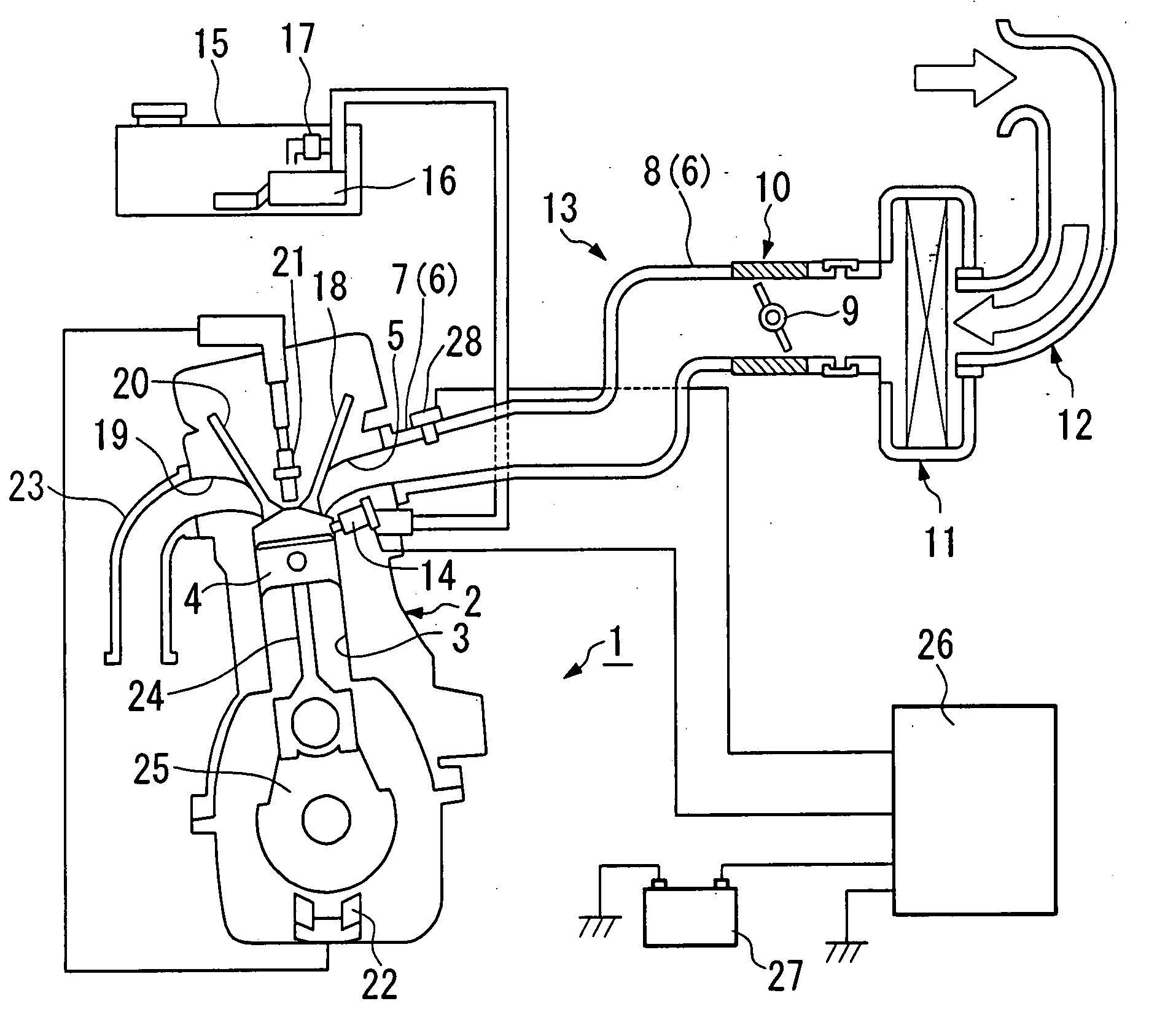
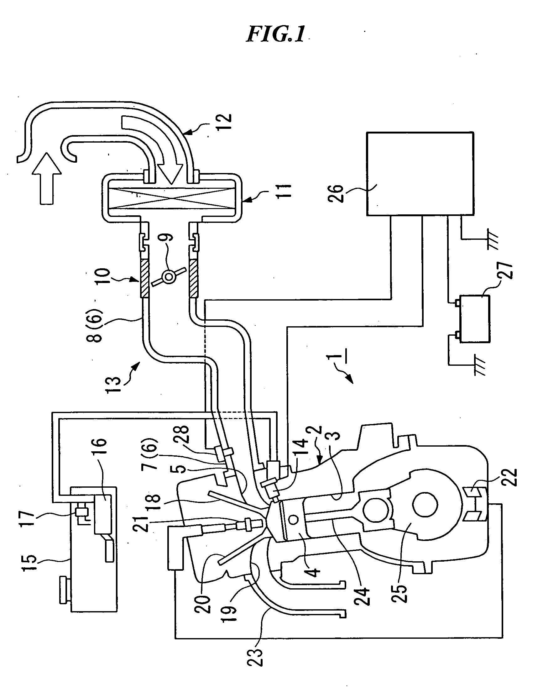
[0012] An embodiment of the present invention will be explained below based on the drawings.

[0013] As shown in FIG. 1, an engine (internal combustion engine) 1 is a multi-cylinder reciprocating engine in which each piston 4 undergoes reciprocating linear motion in a plurality of cylinders 3 of an engine main body 2. The reciprocating motion of the piston 4 changes the volume in the cylinder 3, repeating each stroke of air intake, compression, combustion (expansion), and exhaust. Branch pipes 7 are positioned downstream from an air intake manifold 6 in the direction of air intake. Each of the branch pipes 7 is coupled to an external opening portion of an air intake port 5 which corresponds to each cylinder of the engine main body 2. A collecting pipe 8 is positioned at the upstream from the air intake manifold 6 in the direction of air intake. The collecting pipe 8 is coupled to a throttle body 10 having throttle valve 9 for adjusting air quantity (air intake quantity) which is suct...


PUM


Abstract

A control apparatus is for an engine of a direct cylinder fuel-injection type that directly injects a fuel in a combustion chamber of a cylinder. The control apparatus includes an air flow meter which is positioned downstream from a throttle valve located in an air intake passage of the engine and which measures a quantity of air suctioned into the engine, and a control circuit which calculates a fuel injecting quantity in accordance with measurement information outputted from the air flow meter and which outputs a signal to an injector.

Description

TECHNICAL FIELD [0001] The present invention relates to a control apparatus for controlling fuel injection in an internal combustion engine having direct cylinder fuel-injection. Priority is claimed on Japanese Patent application No. 2003-115908, filed Apr. 21, 2003, the content of which is incorporated herein by reference. BACKGROUND ART [0002] Some internal combustion engines for vehicles provide a throttle valve at the upstream side of intake manifolds (air intake passages), and provide a fuel injection valve and an air flow rate sensor at the downstream side of the throttle valve (for example, refer to Japanese Examined Patent Application, Second Publication No. H04-15388). An intake air volume signal which is an output from the air flow rate sensor is input to a control circuit, and a fuel injection quantity is calculated in response to the operational state of the internal combustion engine. In addition, an injection quantity signal based on the calculated fuel injection quant...

Claims


Application Information

Patent Timeline
IPC IPC(8): F02D41/18F02D41/02F02D45/00
CPCF02D41/182
Inventor YATABE, FUMIO
Owner KEIHIN CORP
Why Eureka
Try Eureka