Device and method for cleaning photomask

Active Publication Date: 2006-09-21
PKL
View PDF5 Cites 35 Cited by
  • Summary
  • Abstract
  • Description
  • Claims
  • Application Information

AI Technical Summary

Benefits of technology

[0007] Accordingly, the present invention has been made keeping in mind the above problems occurring in the prior art, and an object of the present invention is to provide a device and a method of cleaning a photomask, in which heat treatment is conducted after a cleaning process in order to remove residual ions from the surface of the mask, and consequently, haze is prevented and optical property changes to a phase shift mask are reduced.

Problems solved by technology

A conventional wet cleaning device and method is problematic in that it cannot completely remove such haze.

Method used


Image

  • Device and method for cleaning photomask
  • Device and method for cleaning photomask
  • Device and method for cleaning photomask

Examples


Embodiment Construction

[0035] Hereinafter, a detailed description will be given of the present invention, referring to the accompanying drawings.

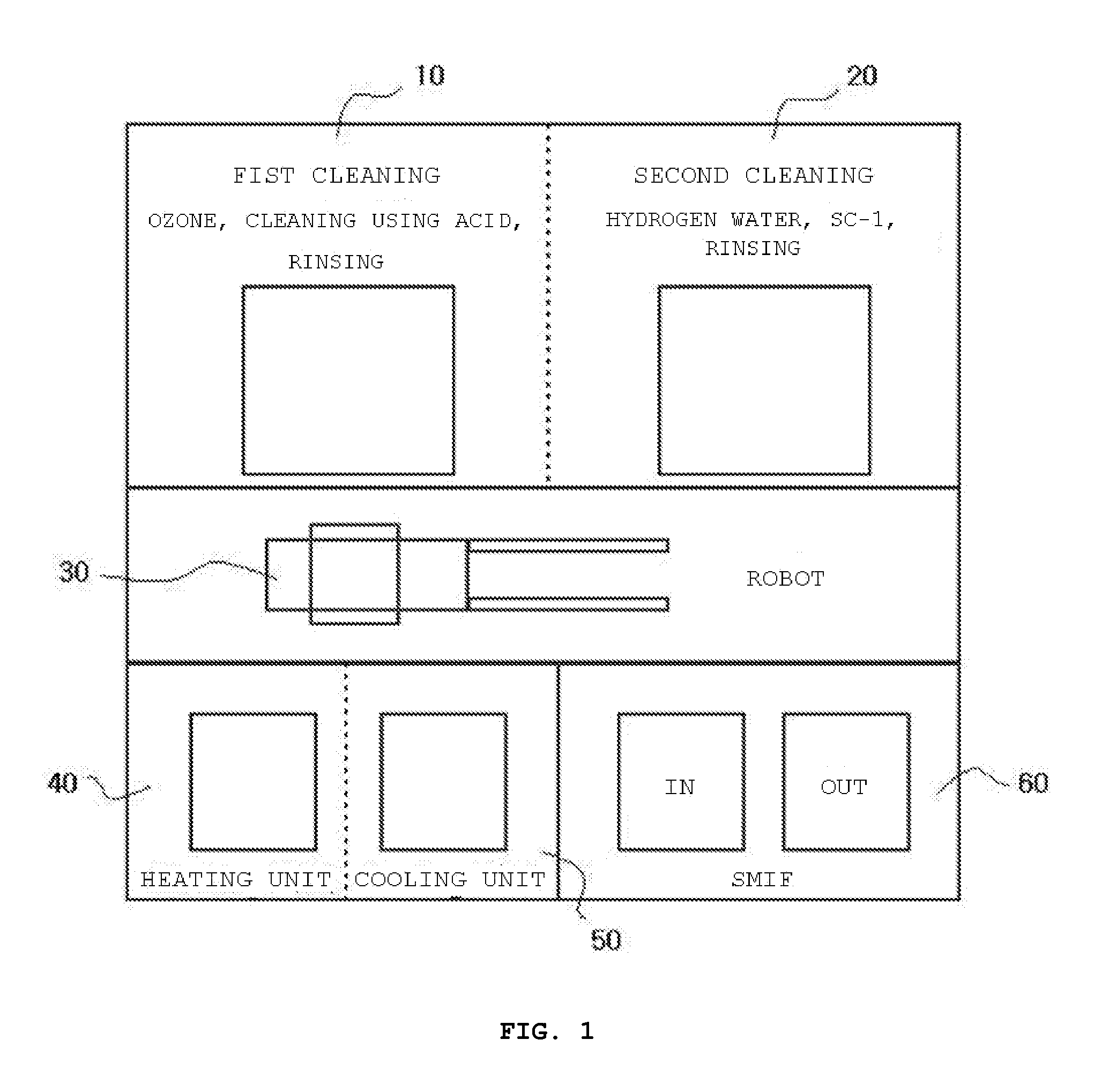
[0036]FIG. 1 illustrates a device for cleaning a photomask according to the present invention.

[0037] As shown in FIG. 1, the device for cleaning a photomask according to the present invention comprises a first cleaning unit 10, a second cleaning unit 20, a robot arm 30, a heat treating unit 40, a cooling unit 50, and a photomask carrier 60.

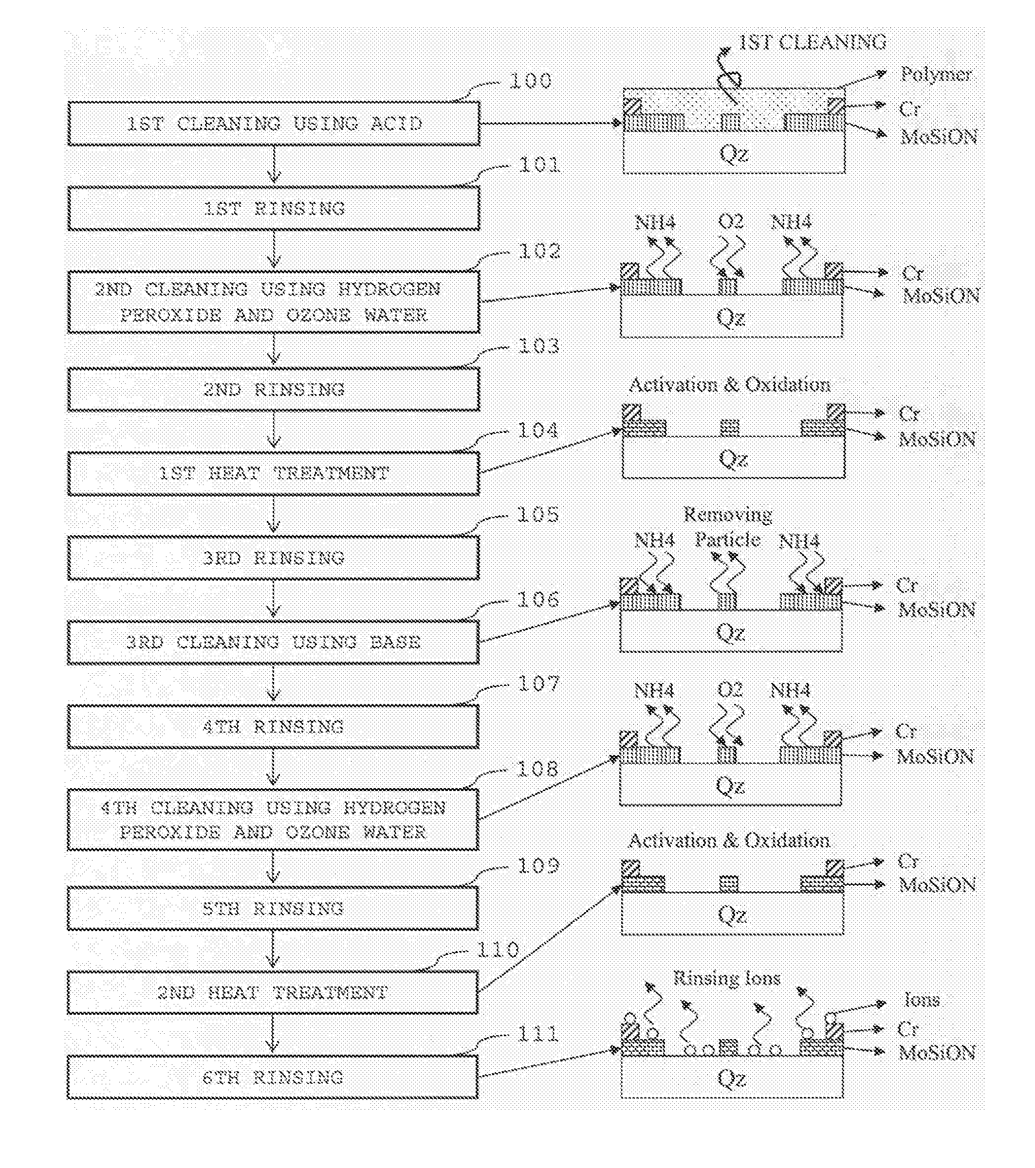
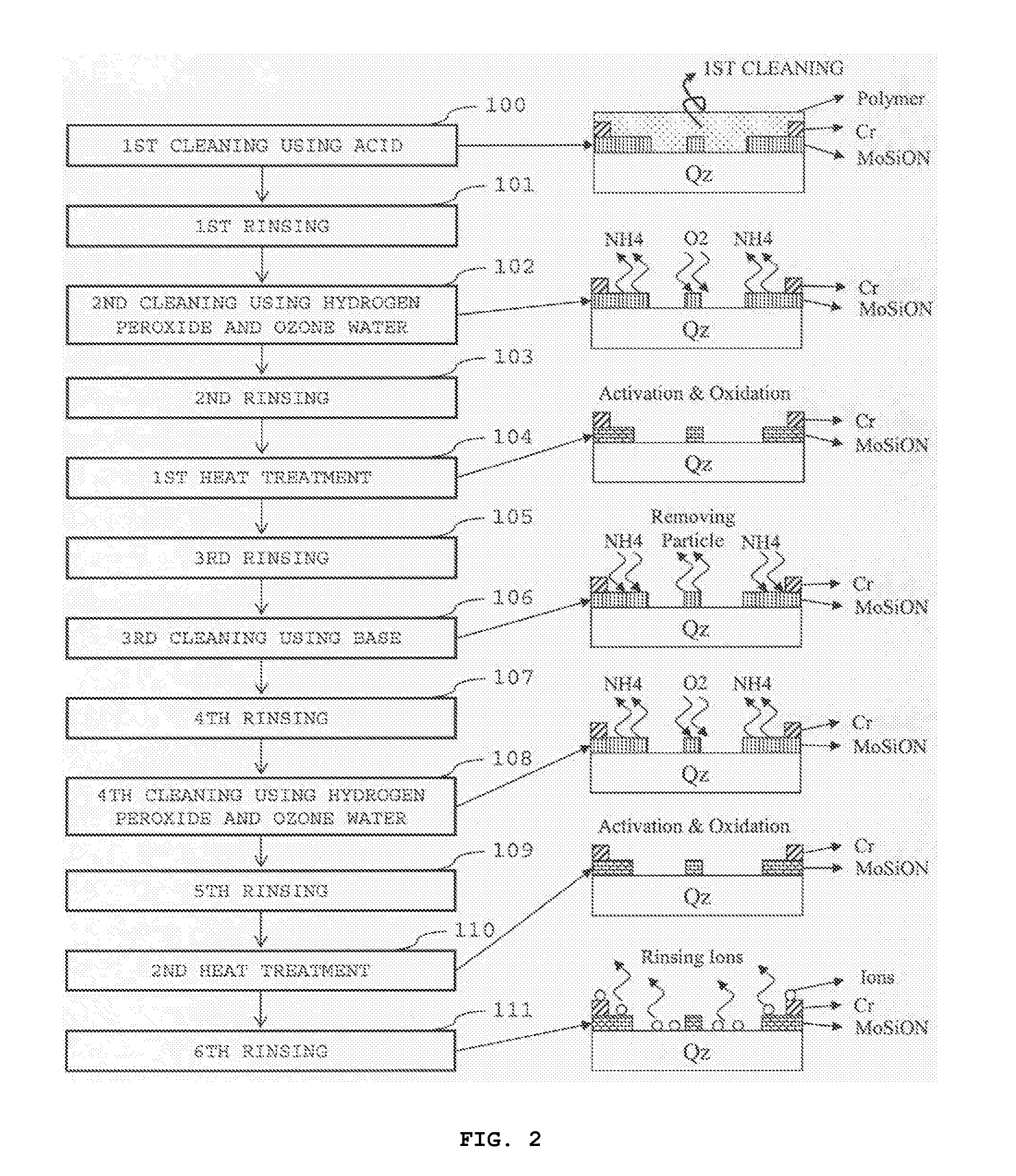
[0038] The first cleaning unit 10 cleans the photomask using acids to remove a polymer formed on the photomask.

[0039] Furthermore, the second cleaning unit 20 cleans the photomask using bases.

[0040] As well, the robot arm 30 carries the photomask.

[0041] Additionally, the heat treating unit 40 heat treats the photomask, which was cleaned using the acids and bases.

[0042] In the present embodiment, illustrative, but, non-limiting, examples of the heat treating unit include an electric heating furnace and a convection oven. ...


PUM

PropertyMeasurementUnit
Temperatureaaaaaaaaaa
Hazeaaaaaaaaaa
Optical propertiesaaaaaaaaaa

Abstract

Disclosed herein is a device and a method of cleaning a photomask, which prevents haze from being generated on a surface of the photomask during a photolithography process. The photomask is heat treated to remove residual ions on a surface thereof and to induce curing and oxidation of Cr and MoSiON layers, thereby preventing diffusion of the ions. Etching of Cr and MoSiON layers due to a cleaning process is suppressed in order to significantly reduce a change in phase and transmissivity of optical properties of Cr and MoSiON.

Description

BACKGROUND OF THE INVENTION [0001] 1. Field of the Invention [0002] The present invention relates to a cleaning device and method. More particularly, the present invention pertains to a device and a method of cleaning a photomask that prevent haze from being generated on a surface of the photomask during a photolithography process. [0003] 2. Description of the Related Art [0004] In accordance with increased integration of semiconductor devices, wavelengths of exposure sources are becoming shorter and shorter in order to improve the resolution of patterns. Accordingly, a haze, which is not formed in a conventional wavelength band, may occur. In a conventional photolithography process at a wavelength above an I-line, exposing energy is relatively low, thus a phenomenon in which residual ions, such as SOx, NOx, POx, F, Cl, NH4, Ca, and Mg, on a surface of a photomask cause an optical reaction does not occur. [0005] However, at a light source of 248 nm or less, exposing energy is increa...

Claims


Application Information

Patent Timeline
IPC IPC(8): B08B7/00B08B3/00B08B3/08G03F1/82
CPCG03F1/32G03F1/82H01L21/67207
Inventor KIM, YONG DAEKIM, JONG MINKANG, HAN BYULCHO, HYUN JOONCHOI, SANG SOO
Owner PKL
Why Eureka
Try Eureka