Imaging-based bar code symbol reading system permitting modification of system features and functionalities without detailed knowledge about the hardware platform, communication interfaces, or user interfaces

a bar code symbol and reading system technology, applied in the field of hand-supportable and portable areatype digital bar code readers, can solve the problems of code reading systems that have limited their performance, limit the capability of such systems from reading big, and the limitations of the ability of such systems to perform the job

Active Publication Date: 2006-09-21
METROLOGIC INSTR
View PDF99 Cites 48 Cited by
  • Summary
  • Abstract
  • Description
  • Claims
  • Application Information

AI Technical Summary

Benefits of technology

[0035] Accordingly, a primary object of the present invention is to provide a novel method of and apparatus for enabling the reading of 1D and 2D bar code symbologies using image capture and processing based systems and devices, which avoid the shortcomings and drawbacks of prior art methods and apparatus.

Problems solved by technology

Prior art imaging-based bar code symbol readers suffer from a number of additional shortcomings and drawbacks.
Consequently, the statically-configured nature of such prior art imaging-based bar code reading systems has limited their performance.
This limits the capabilities of such systems from reading big or highly dense bar code labels.
While this method has been proven for the CCD-based bar code scanners, it is not suitable, however, for the CMOS-based image sensing devices, which require a more sophisticated shuttering mechanism, leading to increased complexity, less reliability and, ultimately, more expensive bar code scanning systems.
Also, due to the complexity of the hardware platforms of such prior art imaging-based bar code symbol readers, end-users are not permitted to modify the features and functionalities of such system to their customized application requirements, other than changing limited functions within the system by reading system-programming type bar code symbols, as disclosed in U.S. Pat. Nos. 6,321,989; 5,965,863; 5,929,418; 5,932,862, each being incorporated herein by reference.
Also, dedicated image-processing based bar code symbol reading devices usually have very limited resources, such as the amount of volatile and non-volatile memories.
Therefore, they usually do not have a rich set of tools normally available to universal computer systems.
This software modification process is both costly and time consuming.
Finally, as a result of limitations in the mechanical, electrical, optical, and software design of prior art imaging-based bar code symbol readers, such prior art readers generally (i) fail to enable users to read high-density 1D bar codes with the ease and simplicity of laser scanning based bar code symbol readers, and also 2D symbologies, such as PDF 417 and Data Matrix, and (ii) of have been less than ideal for use in OCR and OCV, security applications, etc.
; and (iii) end-users are not able to modify the features and functionalities of such prior art systems without detailed knowledge about the hard-ware platform of such system.

Method used


Image

  • Imaging-based bar code symbol reading system permitting modification of system features and functionalities without detailed knowledge about the hardware platform, communication interfaces, or user interfaces
  • Imaging-based bar code symbol reading system permitting modification of system features and functionalities without detailed knowledge about the hardware platform, communication interfaces, or user interfaces
  • Imaging-based bar code symbol reading system permitting modification of system features and functionalities without detailed knowledge about the hardware platform, communication interfaces, or user interfaces

Examples


Embodiment Construction

[0231] Referring to the figures in the accompanying Drawings, the various illustrative embodiments of the hand-supportable imaging-based bar code symbol reading system of the present invention will be described in great detail, wherein like elements will be indicated using like reference numerals.

Hand-Supportable Digital Imaging-Based Bar Code Reading Device of the First Illustrative Embodiment of the Present Invention

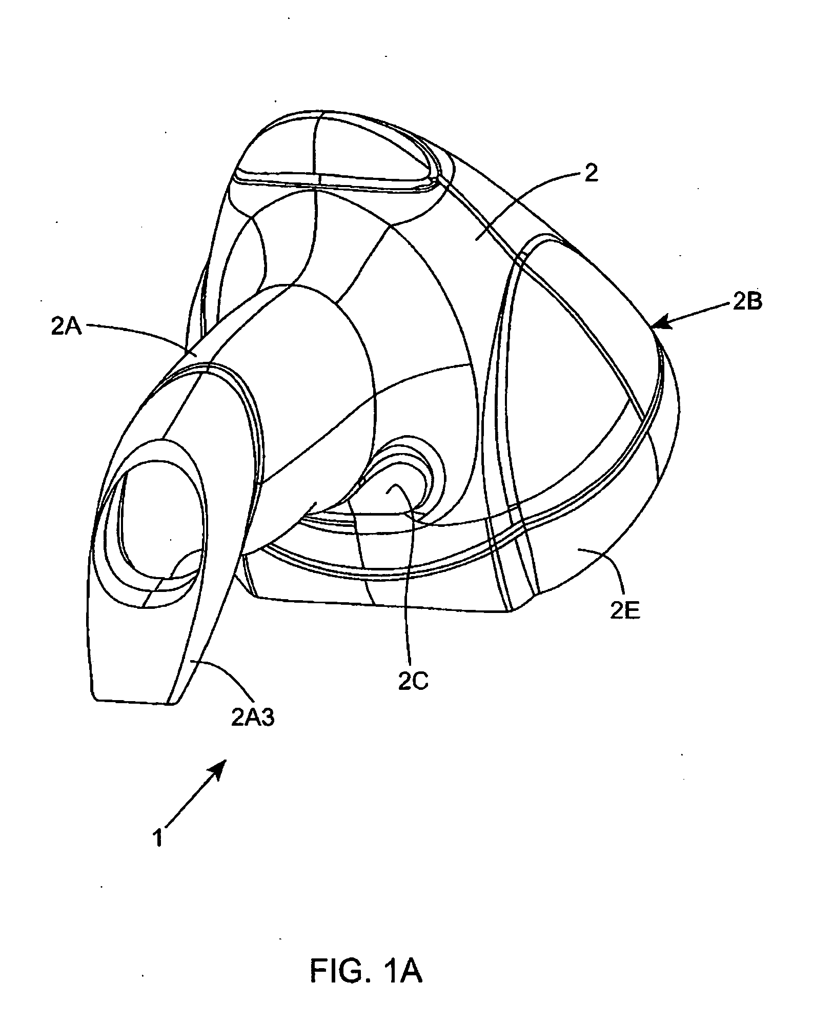
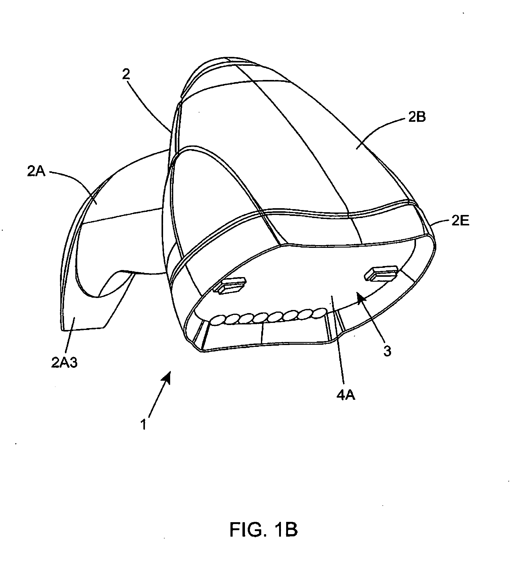
[0232] Referring to FIGS. 1A through 1K, the hand-supportable digital imaging-based bar code symbol reading device of the first illustrative embodiment of the present invention 1 is shown in detail comprising a hand-supportable housing 2 having a handle portion 2A and a head portion 2B that is provided with a light transmission window 3 with a high-pass (red-wavelength reflecting) optical filter element 4A having light transmission characteristics set forth in FIG. 5A2, in the illustrative embodiment. As will be described in greater detail hereinafter, high-pass opt...


PUM


Abstract

Disclosed is an image capture and processing system that supports manufacturer-constrained system behavior modification by the end_user through the development and installation/deployment of plug-in modules within the application layer of the system by a person other than the system designer, so as to allow this person to flexible modify prespecified features and functionalities of the system, and thus satisfy customized end-user application requirements, but without requiring detailed knowledge about the hard-ware platform of the system.

Description

RELATED CASES [0001] This Application is a Continuation-in-Part of the following U.S. applications Ser. No. 10 / 989,220 filed Nov. 15, 2004; Ser. No. 10 / 712,787 filed Nov. 11, 2003; Ser. No. 10 / 893,800 filed Jul. 16, 2004; Ser. No. 10 / 893,797 filed Jul. 16, 2004; Ser. No. 10 / 893,798 filed Jul. 16, 2004; Ser. No. 10 / 894,476 filed Jul. 16, 2004; Ser. No. 10 / 894,478 filed Jul. 19, 2004; Ser. No. 10 / 894,412 filed Jul. 19, 2004; Ser. No. 10 / 894,477 filed Jul. 19, 2004; Ser. No. 10 / 895,271 filed Jul. 20, 2004; Ser. No. 10 / 895,811 filed Jul. 20, 2004; Ser. No. 10 / 897,390 filed Jul. 22, 2004; Ser. No. 10 / 897,389 filed Jul. 22, 2004; Ser. No. 10 / 901,463 filed Jul. 27, 2004; Ser. No. 10 / 901,426 filed Jul. 27, 2004; Ser. No. 10 / 901,446 filed Jul. 27, 2004; Ser. No. 10 / 901,461 filed Jul. 28, 2004; Ser. No. 10 / 901,429 filed Jul. 28, 2004; Ser. No. 10 / 901,427 filed Jul. 28, 2004; Ser. No. 10 / 901,445 filed Jul. 28, 2004; Ser. No. 10 / 901,428 filed Jul. 28, 2004; Ser. No. 10 / 902,709 filed Jul. 29, 20...

Claims


Application Information

Patent Timeline
Patent Type & Authority Applications(United States)
IPC IPC(8): G06K7/10G06F
CPCG06K7/10881G06K7/14
Inventor KOTLARSKY, ANATOLYZHU, XIAOXUN
Owner METROLOGIC INSTR
Why Eureka
Try Eureka