

Armature, method for manufacturing the armature, and direct current motor
Patent Information
- Authority / Receiving Office
- US · United States
- Current Assignee / Owner
- ASMO CO LTD
- Publication Date
- 2006-09-21
- Estimated Expiration
- Not applicable · inactive patent
Smart Images
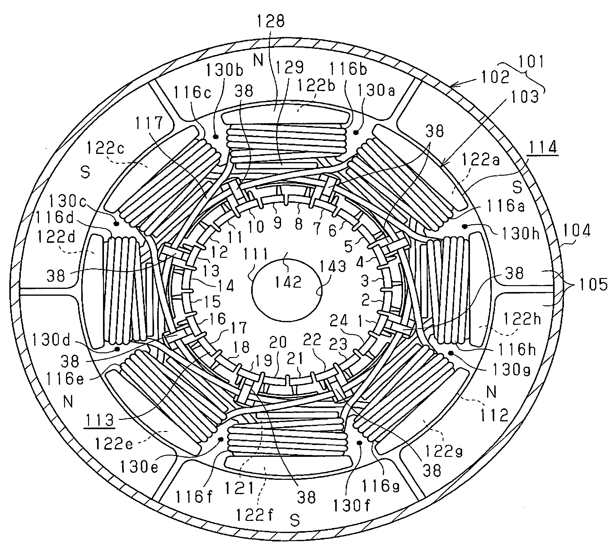
Figure 1 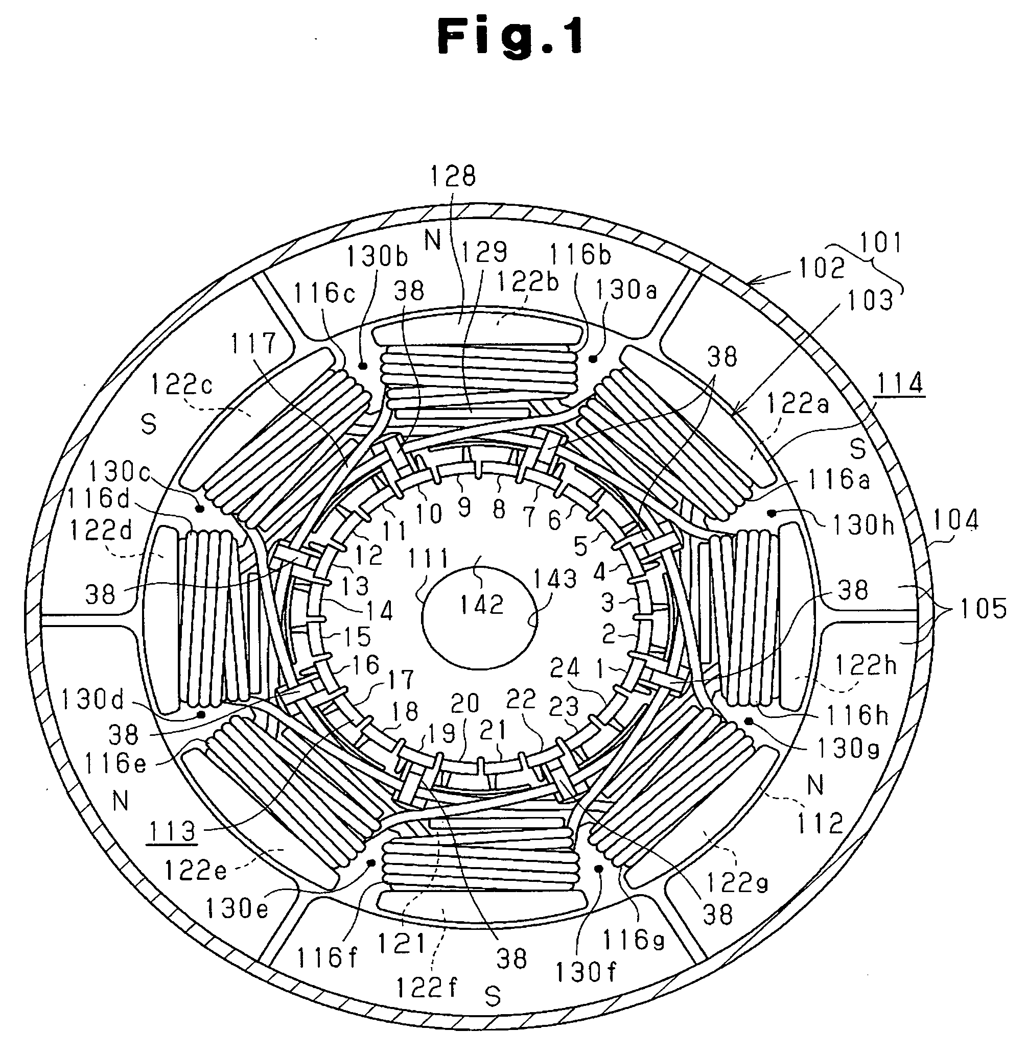
Figure 2 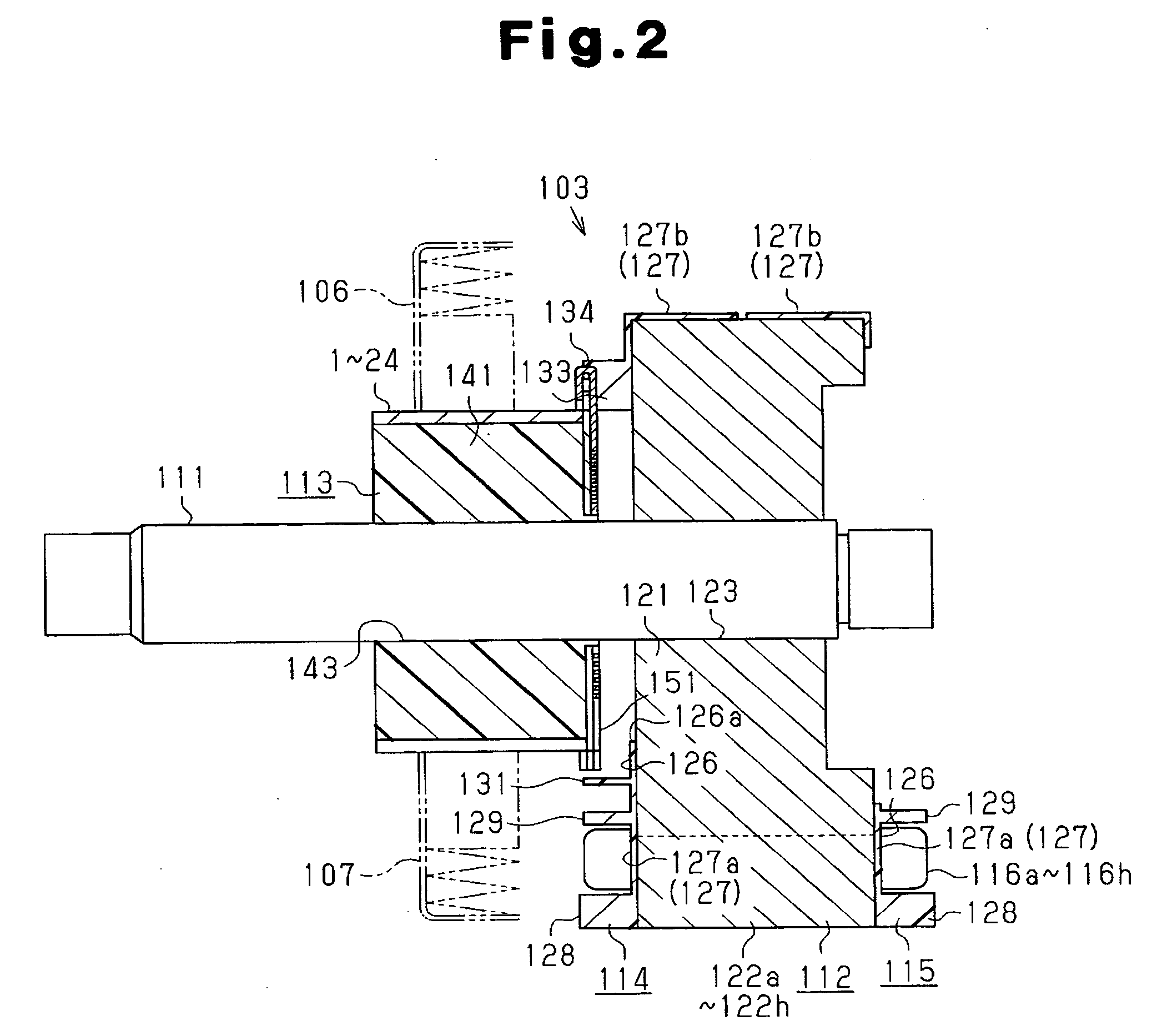
Figure 3
Abstract
Description
BACKGROUND OF THE INVENTION
[0001] The present invention relates to an armature and a manufacturing method therefor, and a DC motor.
[0002] A general DC motor with brushes is provided with a plurality of coils wound on a core and a commutator having a plurality of segments connected electrically to these coils, and the core and the commutator are fixed on a rotary shaft so as to be arranged along the axis of the rotary shaft. In a DC motor disclosed, for example, in Japanese Laid-Open Patent Publication No. 2003-299292, the end portion of a conductor forming the coil is engaged with a claw portion provided on a segment, and thereby the coil is connected electrically to the segment.
[0003] For the DC motor described in the above publication, a step is required in which after the coils have been wound on the core, the end portion of the conductor forming each coil is moved to the position of the claw portion of segment and is engaged to the claw portion. This requirement increases the...