Pixel mirror based stage lighting system

a technology of stage lighting and mirrors, applied in lighting apparatus, light sources, instruments, etc., can solve the problems of less power, brighter, and hence more power-intensive bulbs, and the loss of light in digital mirrors, so as to avoid noise danger

Inactive Publication Date: 2006-09-21
PRODN RESOURCE GROUP L L C
View PDF18 Cites 12 Cited by
  • Summary
  • Abstract
  • Description
  • Claims
  • Application Information

AI Technical Summary

Benefits of technology

[0008] According to an aspect of the embodiment, the second control element is affected out entirely by a programmable gate array, such as a field programmable gate array or similar configurable device. A particularly preferred embodiment reconfigures the device after bulb startup, to avoid noise danger during the bulb startup.

Problems solved by technology

Another aspect is that the digital mirror has loses a certain amount of light.
This has required brighter, and hence more power intensive, bulbs.

Method used


Image

  • Pixel mirror based stage lighting system
  • Pixel mirror based stage lighting system
  • Pixel mirror based stage lighting system

Examples


Embodiment Construction

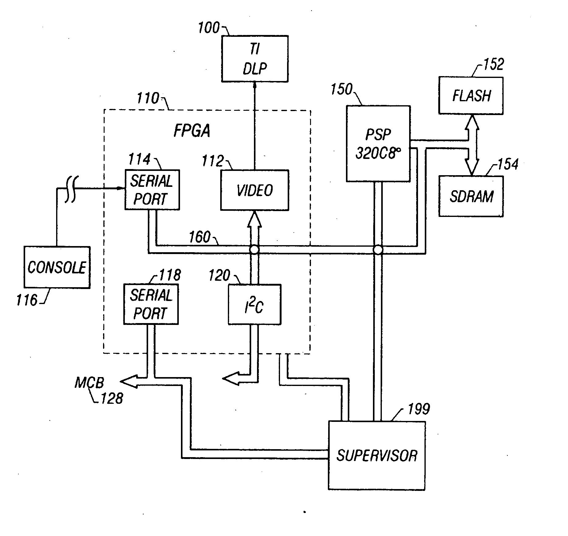
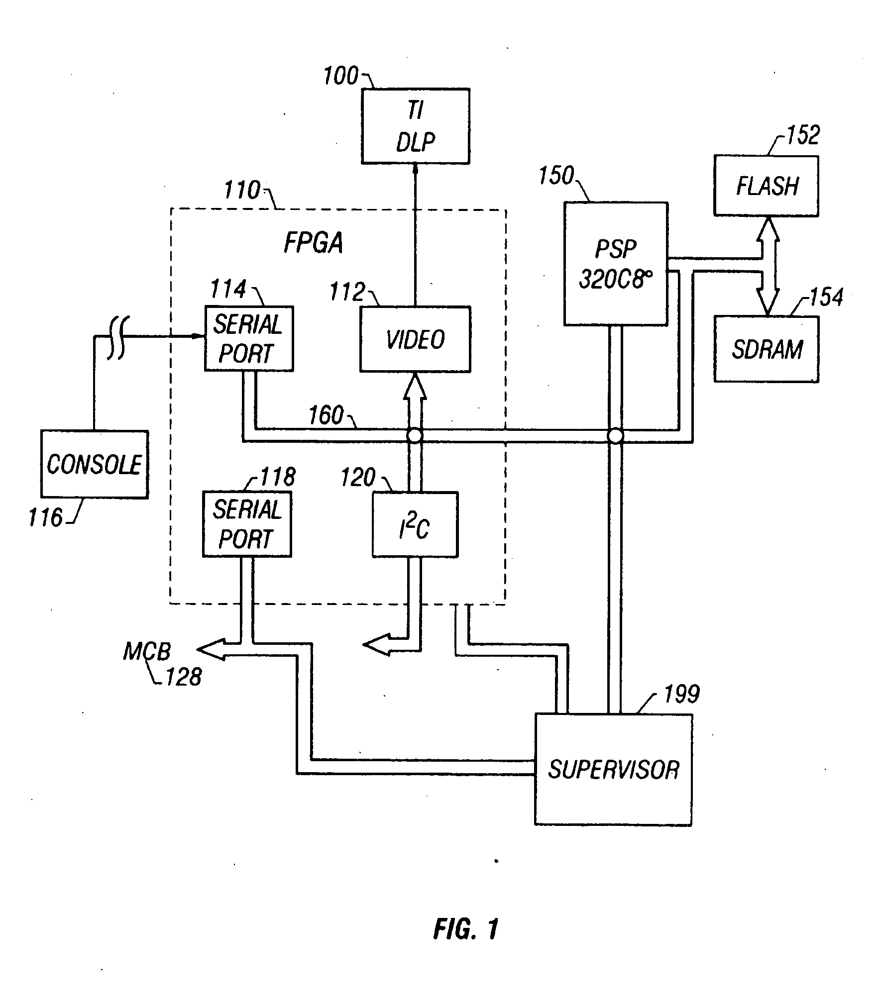
[0020]FIG. 1 shows a block diagram of the electronic control system of the preferred embodiment. The TI DLP board 100 is an off the shelf board from Texas Instruments which carries out control of the digital mirror and other pre-defined functions. Associated functions for control of this system are carried out in a field programmable gate array 110 which is preferably of the electronically reconfigurable type. This device is reconfigured into certain logical devices.

[0021] The video is controlled by a digital signal processor 150, in this case, a 320C80. The digital signal processor (“DSP”) 150 carries out certain operations under control of the user. DSP 150 also includes two different kinds of slave memory, a flash memory 152 which includes the main program for the DSP 150 and which also includes certain shapes for various controlled lights. Certain information is also stored in synchronous DRAM 154. On start up, the initial program is transferred from flash memory 152 into the s...


PUM


Abstract

A lighting system with a digital micromirror device which forms a digital godo system that is controllable on a pixel level. The device includes a number of sensitive electronic elements. The device is controlled by two different controllers: a digital signal processor which is effectively the number crunching portion, and a controller, which controls the functions of the light. The controller also logs errors into a registery, such as a non-volatile memory. A field programmable gate array is used for a number of purposes, including to form the ports. One of those ports is a tech port, which is used to detect status of the light such as faults.

Description

CROSS-REFERENCE TO RELATED APPLICATIONS [0001] This application is a divisional of and claims priority to U.S. application Ser. No. 10 / 658,627, filed Sep. 8, 2003, which is a divisional of U.S. application Ser. No. 10 / 038,182, filed Oct. 24, 2001, now U.S. Pat. No. 6,617,792, which is a divisional of U.S. application Ser. No. 09 / 756,037, filed Jan. 5, 2001, now U.S. Pat. No. 6,515,435, which is a divisional of U.S. application Ser. No. 09 / 145,313, filed Aug. 31, 1998, now U.S. Pat. No. 6,208,087. The disclosures of the prior applications are considered part of (and are incorporated by reference in) the disclosure of this application.BACKGROUND OF THE INVENTION [0002] The present invention describes improvements in a digital mirror stage lighting system. More specifically, the present invention describes techniques which are used to improved operation in the special environment produced by the digital mirror stage lighting system. [0003] Stage lighting systems have increased in compl...

Claims


Application Information

Patent Timeline
Patent Type & Authority Applications(United States)
IPC IPC(8): H05B37/02G02B26/08
CPCG02B26/0841H05B37/029H05B47/155
Inventor HUGHES, MICHAELHEWLETT, WILLIAMCLARKE, IAN
Owner PRODN RESOURCE GROUP L L C
Why Eureka
Try Eureka