Liquid crystal display

a liquid crystal display and liquid crystal technology, applied in the field of liquid crystal display, can solve the problems of image quality deterioration, display contents are blurred, and the performance of the liquid crystal display is inferior to that of the crt, and achieve the effects of improving the blurring of moving images, improving the “color misregistration” of luminance rise time and luminance fall time, and superior display performan

Inactive Publication Date: 2006-09-21
PANASONIC LIQUID CRYSTAL DISPLAY CO LTD +1
View PDF12 Cites 51 Cited by
  • Summary
  • Abstract
  • Description
  • Claims
  • Application Information

AI Technical Summary

Benefits of technology

[0021] It is an object of the present invention to provide a moving image supporting liquid crystal display superior in display performance and successful in improving “color misregistration” in the luminance rise time an

Problems solved by technology

However, when moving images are displayed in a liquid crystal display serving as a personal computer monitor in the background art, there appears an image quality deterioration such as a phenomenon (hereinafter referred to as “moving image blurring”) that the display contents are blurred.
Thus, the performance of the liquid crystal display is inferior to that of a CRT.
However, when the backlight

Method used


Image

  • Liquid crystal display
  • Liquid crystal display
  • Liquid crystal display

Examples


embodiment 1

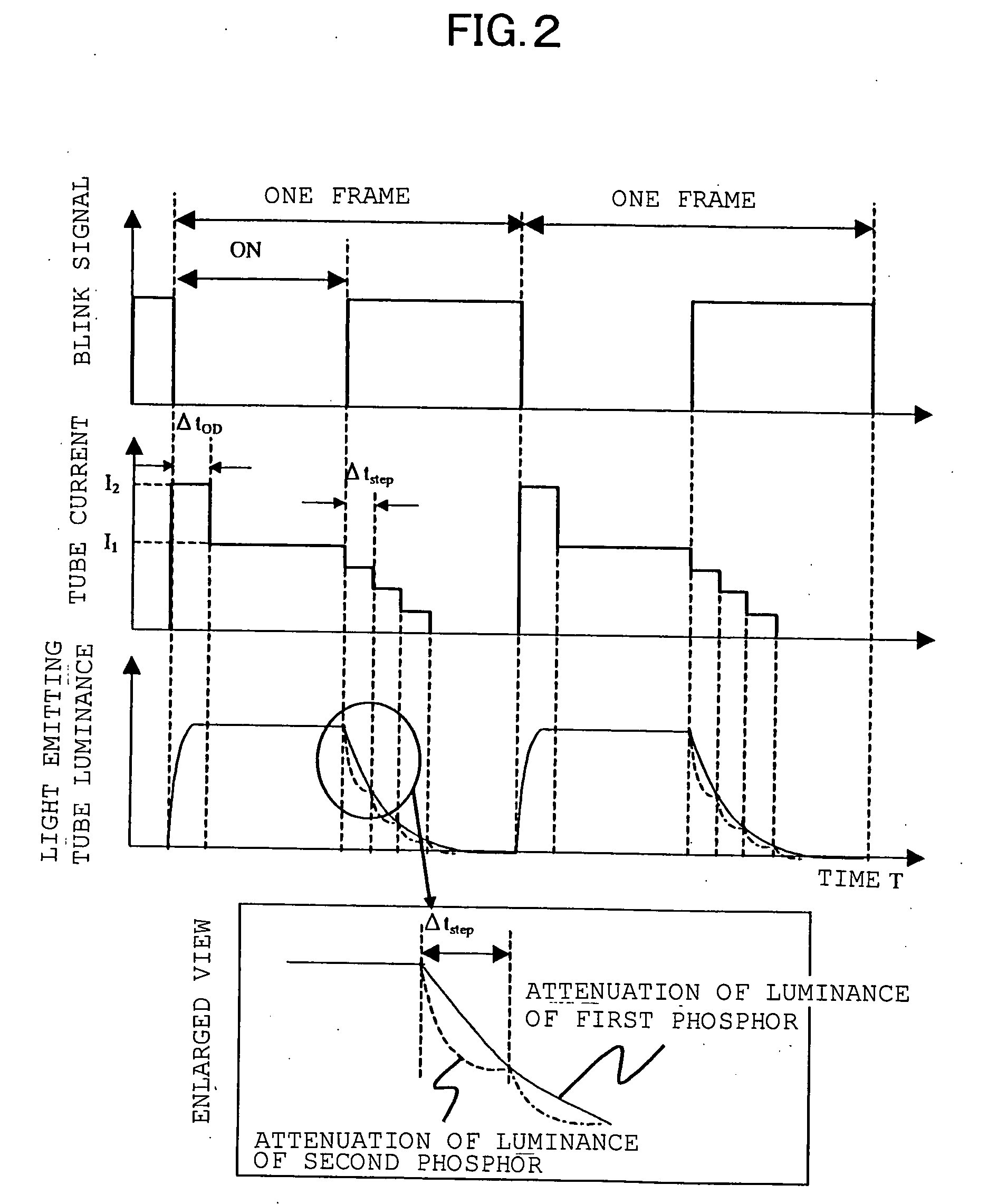
[0102] The outline of a liquid crystal display according to this embodiment is fundamentally similar to the background-art liquid crystal display shown in FIG. 19, but largely different from the background art in the waveform of a current to control the luminance of each fluorescent tube. FIG. 2 shows a blink signal waveform, a tube current waveform and a light emitting tube luminance response waveform in this embodiment.

[0103] In this embodiment, one kind of multicolor light source is used. Specifically, cold cathode fluorescent tubes internally applied with fluorescent materials of three colors (red, green and blue) are used as the light source. The waveform of a current applied to each of the cold cathode tubes is shown in FIG. 2.

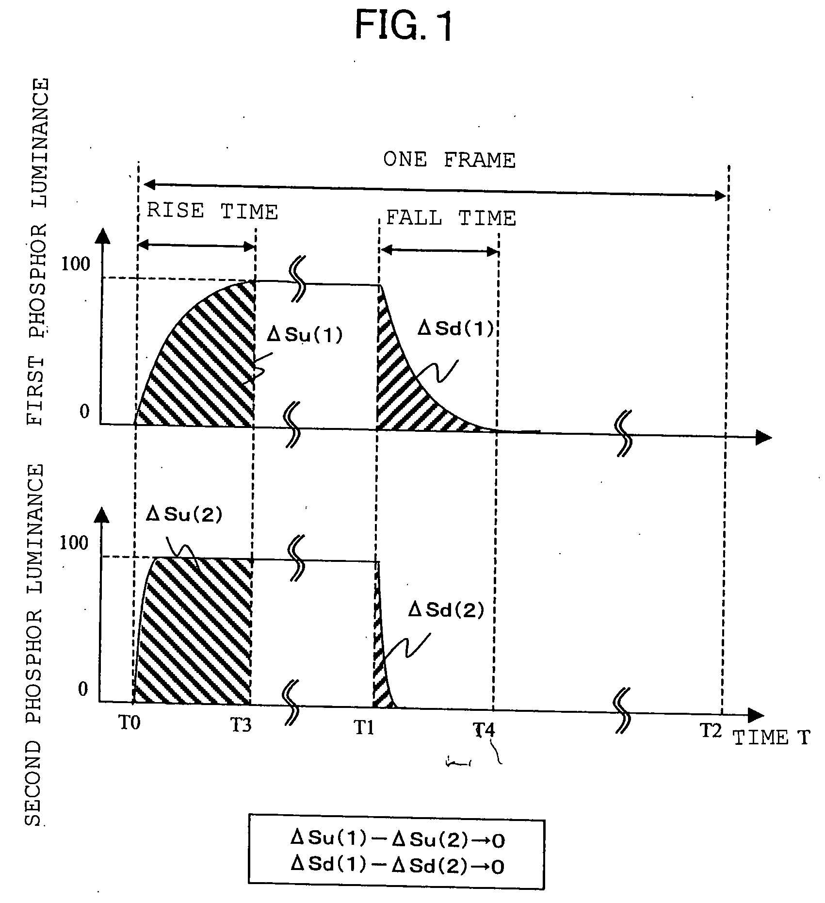
[0104] Here, (Ba,Sr)MgAl10O17:Eu, Y2O3:Eu and LaPO4:Tb,Ce are used as blue, red and green fluorescent materials respectively. The luminance response speeds of these fluorescent materials are about 0.5 msec, 3 msec and 7 msec respectively.

[0105] As sho...

embodiment 2

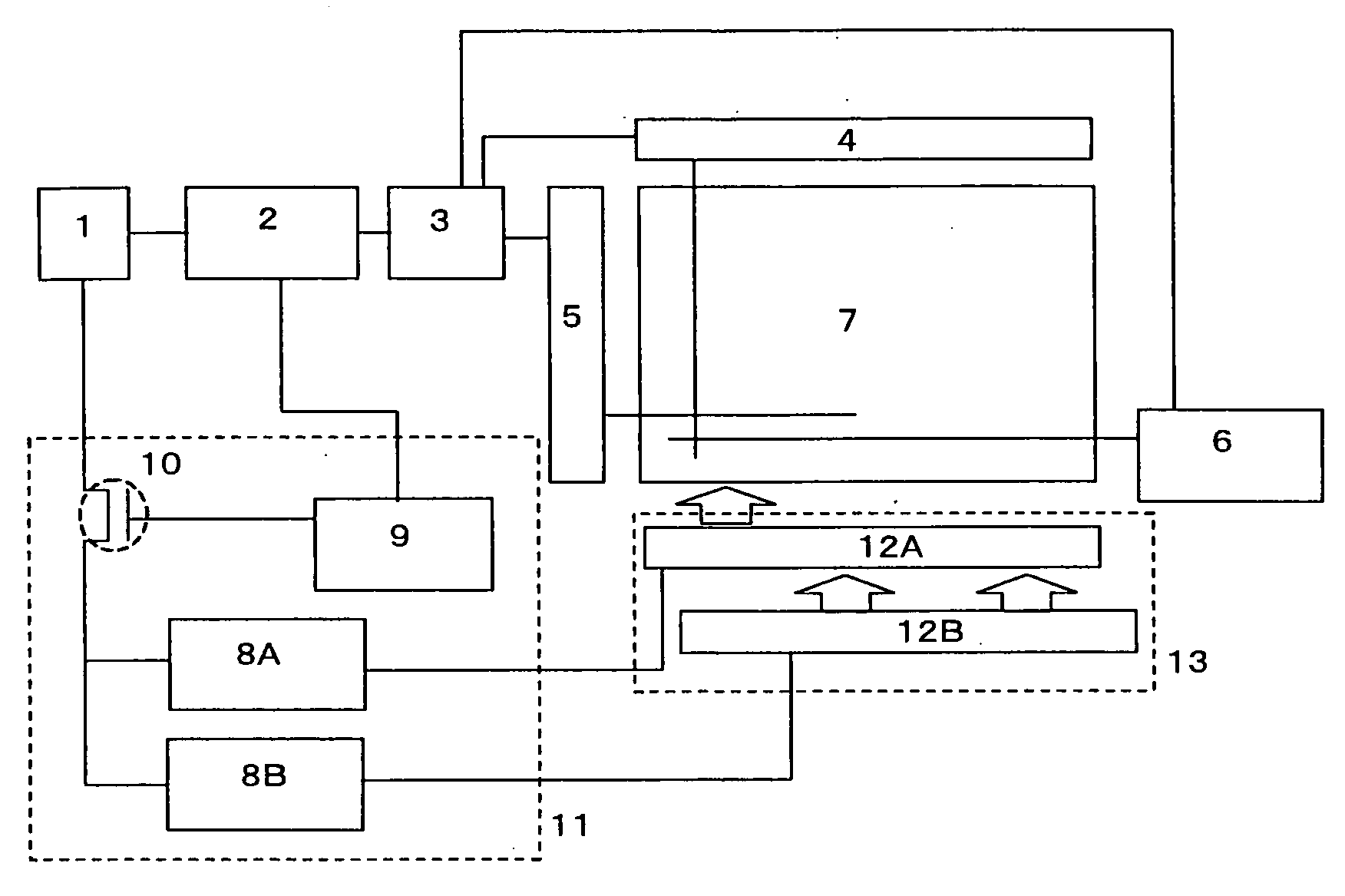
[0108] This embodiment is different from Embodiment 1 only in the waveform of a current to control the luminance of each fluorescent tube. Particularly the current waveform is different in the luminance rise time. The blink waveform, the tube current waveform and the light emitting tube luminance response waveform in this embodiment will be described with reference to FIG. 4. In FIG. 5, the reference numeral 12A represents a first light emitting tube; 12B, a second light emitting tube; and 8A and 8B, inverters for driving the first light emitting tube 12A and the second light emitting tube 12B respectively. The same reference numerals as those in FIG. 19 correspond to the same parts as those in FIG. 19.

[0109] As shown in FIG. 4, in the luminance rise time, the current value is increased stepwise. In this event, the current value is set so that the step width of the current value has a time width Δtstep. It is important to set the time width Δtstep to be shorter than the response ti...

embodiment 3

[0113] The outline of a liquid crystal display according to this embodiment will be described with reference to the aforementioned FIG. 5. In the liquid crystal display according to this embodiment, two kinds of light emitting tubes, that is, a first light emitting tube 12A and a second light emitting tube 12B are used. These two kinds of light emitting tubes are connected to different inverter circuits 8 (8A and 8B), and controlled by one and the same blink signal from a blink signal generation circuit 9 shared by the inverter circuits 8.

[0114] The first light emitting tube 12A is applied with a red fluorescent material and a green fluorescent material having slow response speeds and having almost the same response time. On the other hand, the second light emitting tube 12B is applied with a blue fluorescent material having a fast response speed. Here, (Ba,Sr)MgAl10O17:Eu, Y2O3:Eu and LaPO4:Tb,Ce are used as the blue, red and green fluorescent materials respectively.

[0115] This e...


PUM


Abstract

A liquid crystal display including a blink backlight system light source and a liquid crystal panel for adjusting the amount of light transmitted from the light source. The light source is made of a plurality of light emitting tubes each having one or more kinds of phosphors, and having a turned-on state and a turned-off state within one frame. A luminance factor area of light from each of the phosphors is substantially equal to that of light from any other phosphor in at least one of a luminance rise time when the light source changes from the turned-off state to the turned-on state and a luminance fall time when the light source changes from the turned-on state to the turned-off state.

Description

FIELD OF THE INVENTION [0001] The present invention relates to a liquid crystal display, and particularly relates to a liquid crystal display in which color misregistration is improved to suppress moving image blurring. DESCRIPTION OF BACKGROUND ART [0002] Liquid crystal displays have expanded their market as small-size displays for watches, cellular phones, etc. and as notebook-type personal computer monitors and desktop-type personal computer monitors taking the place of CRTs (Cathode Ray Tubes) due to their features of light weight, low profile and low power consumption. Further, recently, applications of liquid crystal displays have been expanded as monitors or TV sets supporting DVD playback for displaying not only still images but also moving images. Thus, the applications range widely. [0003] However, when moving images are displayed in a liquid crystal display serving as a personal computer monitor in the background art, there appears an image quality deterioration such as a...

Claims


Application Information

Patent Timeline
IPC IPC(8): G09G3/36G02F1/13357G09G3/20G09G3/34
CPCG02F2001/133601G02F2001/133622G09G3/2011G09G3/3406G09G3/3648G09G3/3666G09G2320/0261G09G2310/0237G09G2310/024G09G2310/0251G09G2310/066G09G2310/08G09G2320/0242G09G2310/0221G02F1/133601G02F1/133622
Inventor OKISHIRO, KENJIAONO, YOSHINORIKOMATSU, MASAAKISHIIKI, MASATOSHI
Owner PANASONIC LIQUID CRYSTAL DISPLAY CO LTD
Why Eureka
Try Eureka