Liquid supply apparatus and method, and inkjet recording apparatus

a liquid supply and inkjet technology, applied in the direction of inkjet printing equipment, printing equipment, other printing equipment, etc., can solve the problems of not taking into account the changes in viscosity resistance on the upstream side, the variation of the ejection characteristics of the ejection device, and the inability to correct the variation of pressure loss, so as to achieve a substantially constant pressure loss, minimize the variation of the back pressure of the head, and stable ink supply

Inactive Publication Date: 2006-09-21
FUJIFILM CORP
View PDF1 Cites 20 Cited by
  • Summary
  • Abstract
  • Description
  • Claims
  • Application Information

AI Technical Summary

Benefits of technology

[0008] The present invention has been contrived in view of the foregoing circumstances, an object thereof being to provide a liquid supply apparatus and method, and an inkjet recording apparatus using same, whereby ejection stability can be improved by maintaining the back pressure of the head at a substantially constant level at all times, regardless of the operating environment or ejection conditions (print contents, and the like).

Problems solved by technology

However, although the method disclosed in Japanese Patent Application Publication No. 8-156280 has the beneficial effect of reducing the viscous resistance on the downstream side of a prescribed section (for example, the filter section) of the ink supply system, it does not take account of the changes in viscous resistance on the upstream side.
Furthermore, in an ink supply system which uses ink of high viscosity, such as that described in Japanese Patent Application Publication No. 2003-127417, the pressure loss inside the flow channel is dependent on the ink viscosity changing with the operating temperature conditions, and is also dependent on the ink supply flow speed (ink flow rate), and this can lead to variation in the ejection characteristics of the ejection device.
However, the method disclosed in Japanese Patent Application Publication No. 2003-127417 has no effect in correcting the pressure for pressure loss variations caused by change in the viscosity drag due to change in the ink flow rate.
Furthermore, in Japanese Patent Application Publication No. 2003-127417, the heating system for the whole ink supply system is complicated and large in size, and the temperature control is also complicated.

Method used


Image

  • Liquid supply apparatus and method, and inkjet recording apparatus
  • Liquid supply apparatus and method, and inkjet recording apparatus
  • Liquid supply apparatus and method, and inkjet recording apparatus

Examples


first embodiment

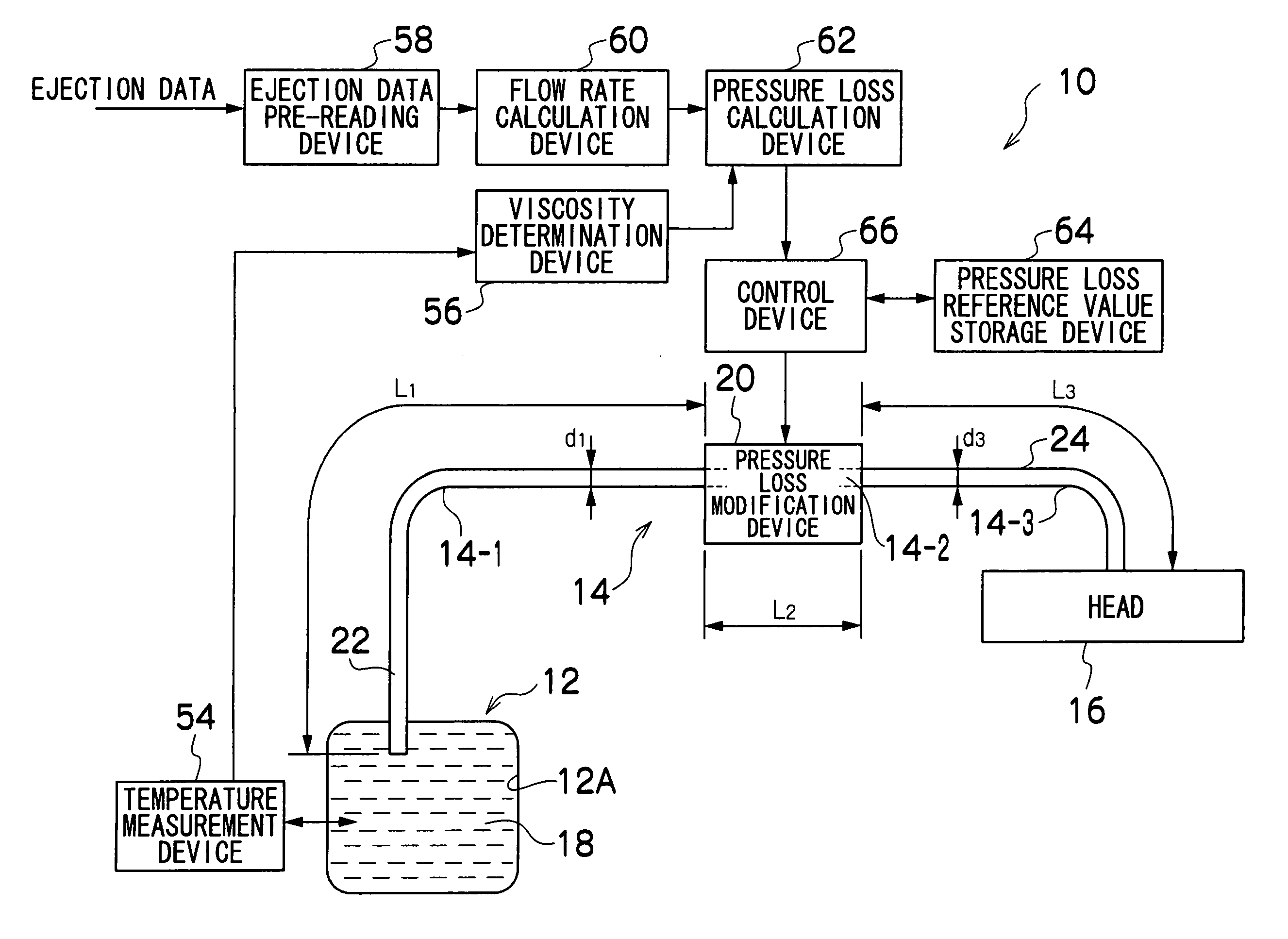
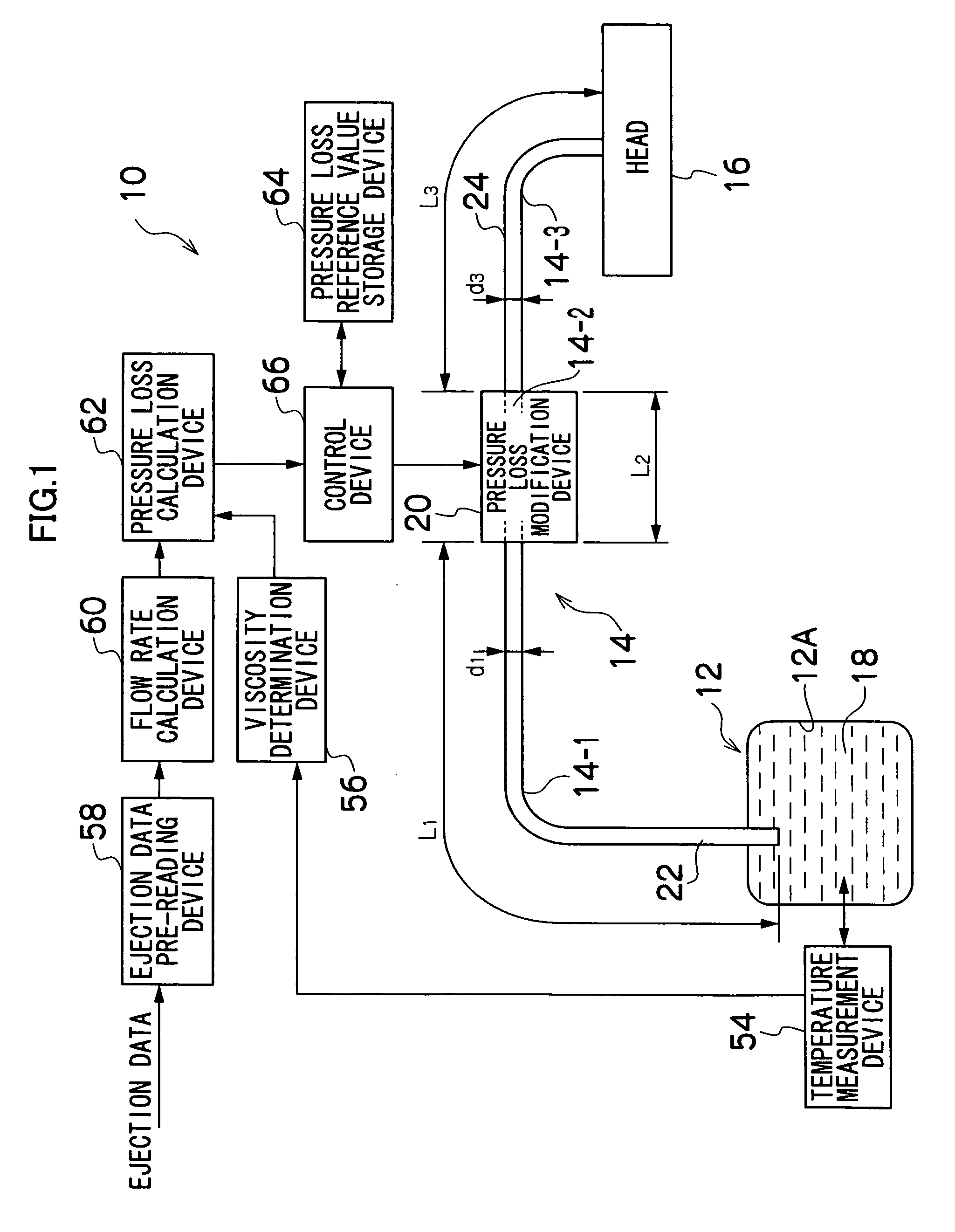
[0054]FIG. 1 is a block diagram showing the general composition of an ink supply apparatus in an inkjet recording apparatus according to a first embodiment of the present invention. As shown in FIG. 1, the ink supply apparatus 10 supplies ink 18 to a print head (corresponding to an ejection head) 16, from an ink tank 12, through an ink supply channel 14, and by controlling a pressure loss modification device 20 provided in a portion of the ink supply channel 14 in accordance with circumstances, the pressure loss in the whole ink supply channel 14 is maintained at a substantially constant level at all times.

[0055] The ink tank 12 is a main tank containing ink to be supplied. The ink tank 12 is formed by a flexible pack, and contains ink 18 sealed inside a flexible container 12A made of resin. As the volume of ink inside the ink tank 12 declines with the consumption of the ink, the container 12A inside the pack is compressed by the atmospheric pressure.

[0056] The ink tank 12 may ado...

second embodiment

[0099]FIG. 7 is a block diagram showing the general composition of an ink supply apparatus in an inkjet recording apparatus according to a second embodiment of the present invention. In FIG. 7, elements which are the same as or similar to the compositional embodiment in FIG. 1 are denoted with the same reference numerals and description thereof is omitted here.

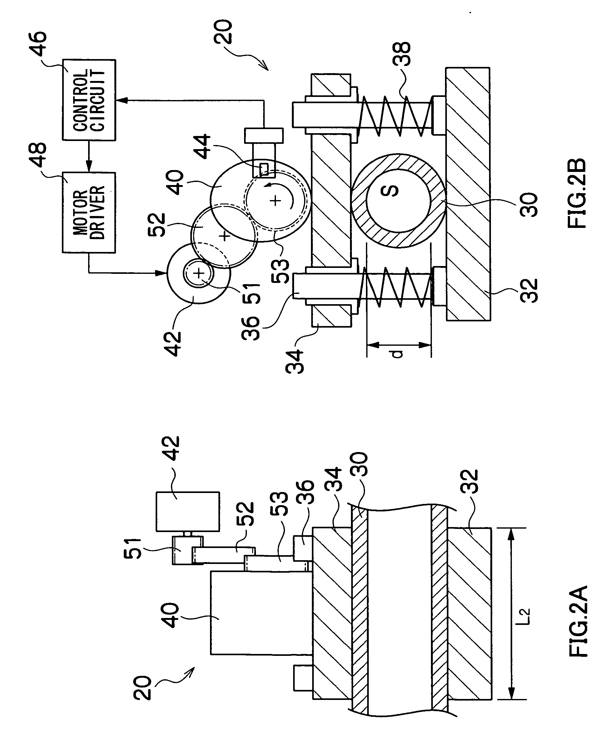
[0100]FIG. 1 shows the embodiment of the mechanism for changing the flow channel diameter, which acts as the pressure loss modification device 20 (see FIGS. 2A and 2B). On the other hand, in the ink supply apparatus 70 shown in FIG. 7, a heating device 72 is provided in a portion of the ink supply channel 14, as a device for changing the pressure loss in the ink supply channel 14. In other words, the ink supply apparatus 70 in FIG. 7 changes the ink viscosity as a control factor which governs the pressure loss in the ink supply channel 14 (namely, it controls the ink viscosity by means of temperature control, on the basis of ...


PUM


Abstract

The liquid supply apparatus supplies liquid for ejection to a liquid ejection head. The apparatus comprises: a tank which stores the liquid; a liquid supply channel through which the liquid in the tank is conveyed to the liquid ejection head; a flow rate determination device which determines a flow rate of the liquid flowing through the liquid supply channel; a pressure loss determination device which determines a pressure loss in a whole of the liquid supply channel according to the flow rate determined by the flow rate determination device; a pressure loss modification device which is disposed in a portion of the liquid supply channel and modifies the pressure loss in the liquid supply channel; and a control device which controls the pressure loss modification device according to the pressure loss in the whole of the liquid supply channel determined by the pressure loss determination device, in such a manner that the pressure loss in the whole of the liquid supply channel remains substantially constant.

Description

BACKGROUND OF THE INVENTION [0001] 1. Field of the Invention [0002] The present invention relates to a liquid supply apparatus and method, and to an inkjet recording apparatus, and more particularly relates to an apparatus and method for supplying liquid for ejection to a liquid ejection head, and an inkjet recording apparatus using the liquid supply apparatus. [0003] 2. Description of the Related Art [0004] An inkjet recording apparatus forms images by supplying ink to a print head (also called a recording head) from an ink tank, through ink supply paths, ejecting ink from nozzles of the print head by selectively driving ejection driving elements (pressure generating elements such as piezoelectric elements, heating elements or the like) corresponding to the respective nozzles, and depositing the ink droplets thus created onto a recording medium. In an inkjet recording apparatus of this kind, it is necessary to achieve stable ink ejection, and many different technologies have been p...

Claims


Application Information

Patent Timeline
Patent Type & Authority Applications(United States)
IPC IPC(8): B41J2/175
CPCB41J2/17596B41J2002/14459B41J2202/20
Inventor KACHI, YASUHIKO
Owner FUJIFILM CORP
Why Eureka
Try Eureka