Image display

a technology of image display and display surface, applied in the field of image display, can solve the problems of disadvantageous partially blocking light emitted from the image display surface, difficult to employ a high-definition display panel with a small pixel pitch, and difficult to provide high-definition images to observers, etc., and achieve the effect of not reducing the brightness of the images observed

Inactive Publication Date: 2006-09-21
EPSON IMAGING DEVICES CORP +1
View PDF3 Cites 27 Cited by
  • Summary
  • Abstract
  • Description
  • Claims
  • Application Information

AI Technical Summary

Benefits of technology

[0016] The present invention has been proposed in order to solve the aforementioned problems, and an object of the present invention is to provide an image display enabli

Problems solved by technology

In the conventional two-screen display 500 shown in FIG. 26, therefore, it is difficult to employ a high-definition display panel having a small pixel pitch.
Consequently, it is difficult to provide high-definition images to the observers 510 and 520 located on different observational positions.
In the three-dimensional image display disclosed in the afore

Method used


Image

  • Image display
  • Image display
  • Image display

Examples


first embodiment

[0062] (First Embodiment)

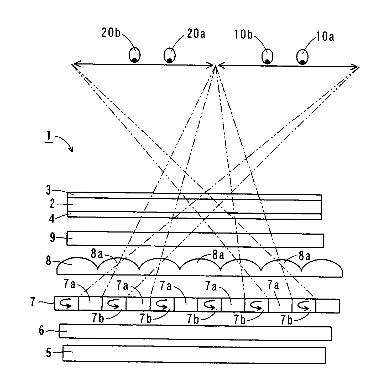
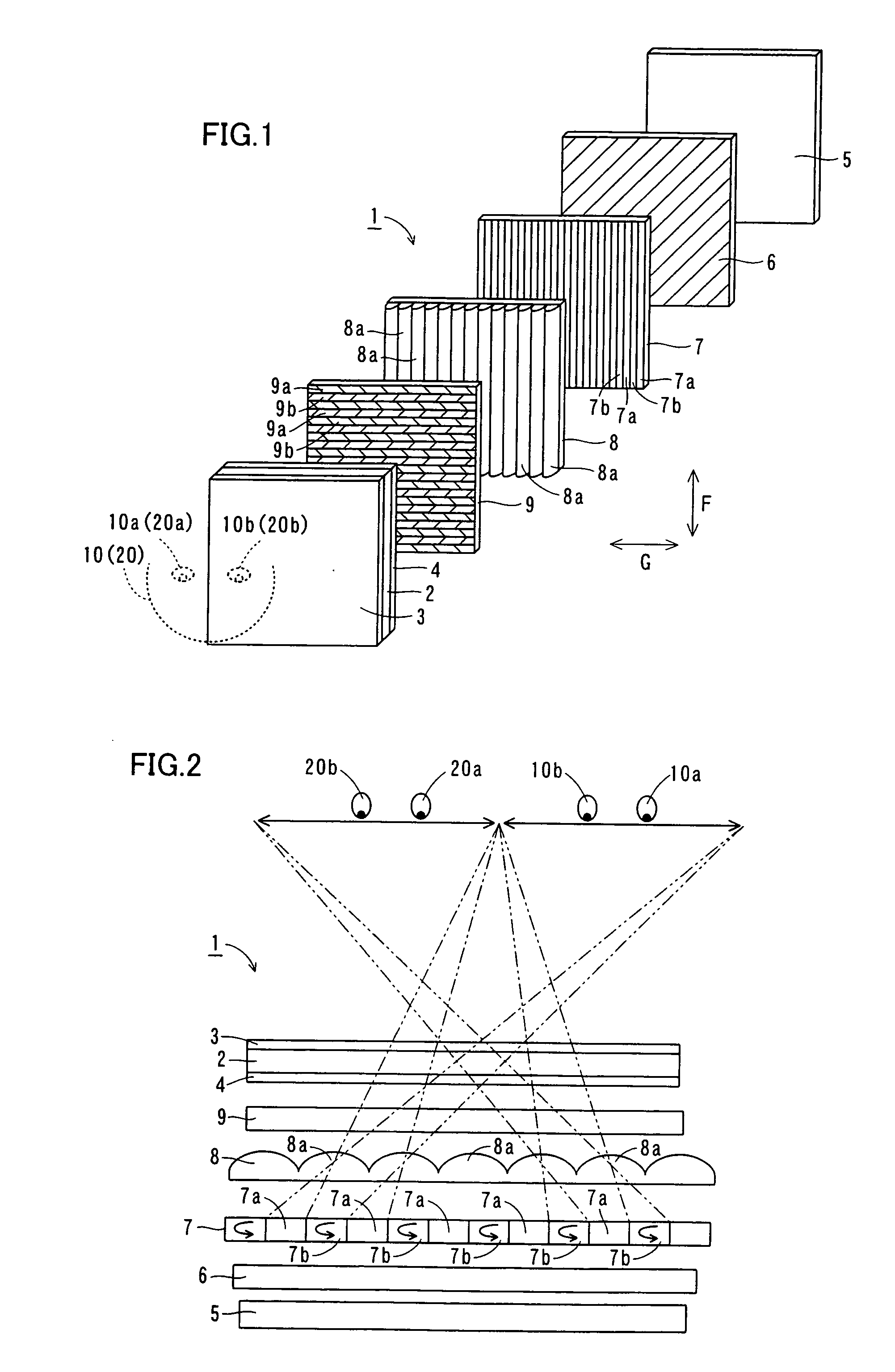
[0063] The structure of an image display 1 according to a first embodiment of the present invention is described with reference to FIGS. 1 to 5.

[0064] As shown in FIGS. 1 and 2, the image display 1 according to the first embodiment of the present invention comprises a display panel 2 for displaying images, polarizing plates 3 and 4 arranged to hold the display panel 2 therebetween, a backlight 5 for irradiating light toward the display panel 2 and still another polarizing plate 6 arranged on a side of the backlight 5 closer to observers 10 and 20 (see FIG. 2). The polarizing plates 3 and 4 arranged to hold the display panel 2 therebetween have polarization axes perpendicular to each other. The polarizing plate 4 has a function of transmitting light having a first polarization axis and absorbing light having a second polarization axis substantially perpendicular to the first polarization axis. The polarizing plate 3 has a function of transmitting light havin...

second embodiment

[0099] (Second Embodiment)

[0100] Referring to FIGS. 3 and 14, an image display 100 according to a second embodiment of the present invention varies display positions of stereoscopic images with movement of the observational position of an observer 10, dissimilarly to the aforementioned first embodiment.

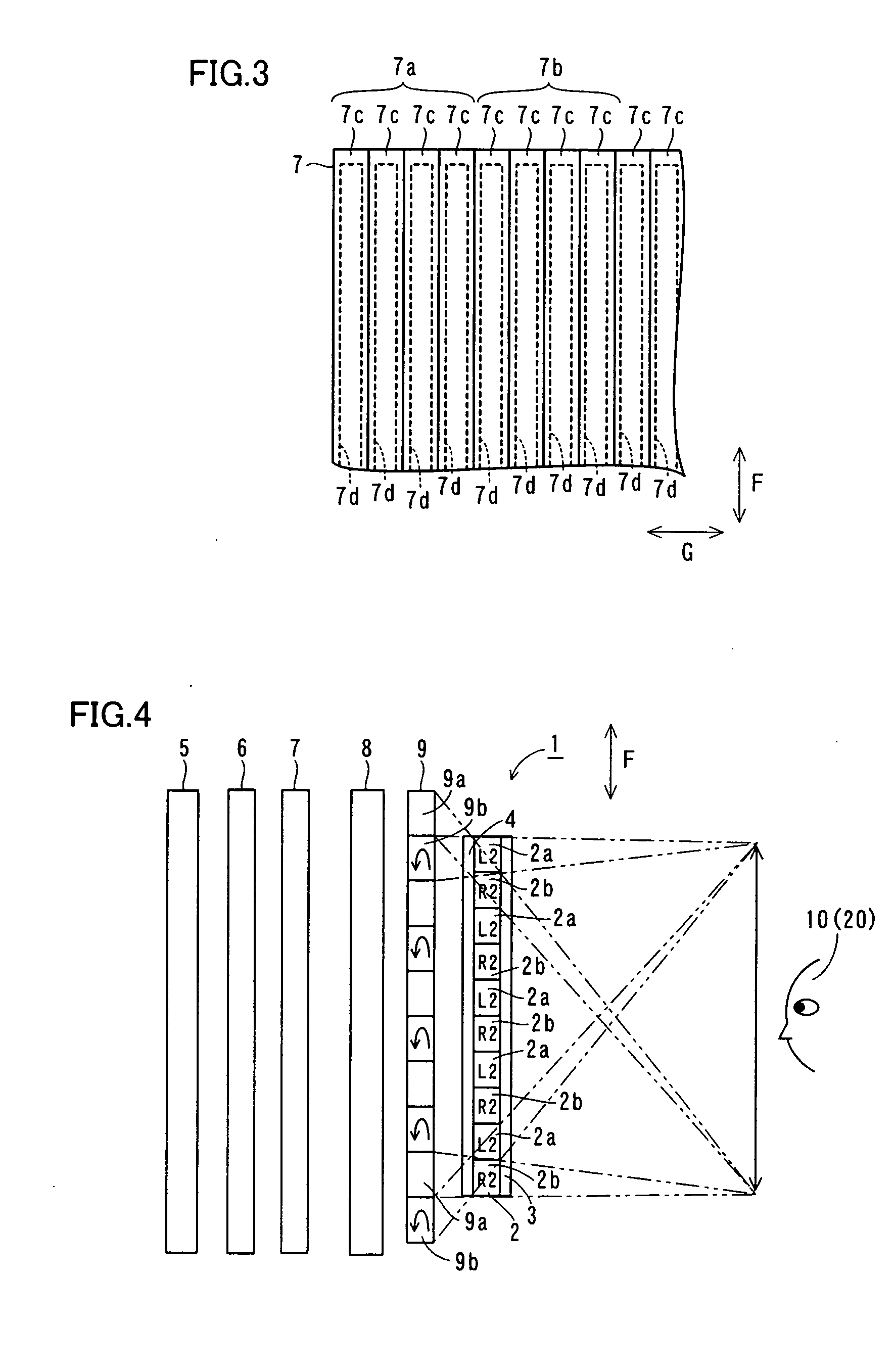
[0101] As shown in FIG. 14, the image display 100 according to the second embodiment comprises a position sensor 130 for sensing the position of the observer 10 and a control portion 140 for moving polarization control areas 7a and 7b of a polarization control liquid crystal panel 7 by controlling application states on electrodes 7d thereof. The position sensor 130 is an example of the “position sensing means” in the present invention. According to the second embodiment, the image sensor 1 constitutes each polarization control area 7a of a unit area 7c (see FIG. 3) by controlling application states on the electrodes 7d (see FIG. 3) of the polarization control liquid crystal panel 7 t...

third embodiment

[0105] (Third Embodiment)

[0106] With reference to FIGS. 2 and 15 to 19, an image display 200 according to a third embodiment of the present invention is described with reference to a method of providing proper orthoscopic images to observers 10 and 20 dissimilarly to the aforementioned first embodiment.

[0107] As shown in FIG. 15, the image display 200 according to the third embodiment comprises a display panel 202 for displaying images, polarizing plates 3 and 4 arranged to hold the display panel 20 therebetween, a backlight 5 for irradiating light toward the display panel 202 and still another polarizing plate 6 arranged on a side of the backlight 5 closer to the observers 10 and 20 (see FIG. 2). The display panel 202 is formed by a glass plate (refractive index n3=about 1.53) having a thickness t1 (e.g., about 0.7 mm). The polarizing plate 4 is formed by a resin plate (refractive index n4=about 1.49) having a thickness t2 (about 0.1 mm).

[0108] A retardation plate 209 is arranged...


PUM


Abstract

An image display comprises polarization axis control means for separating light irradiated from a light source into light having a first polarization axis and another light having a second polarization axis different from the first polarization axis and a lens advancing the light having the first polarization axis and the light having the second polarization axis separated by the polarization axis control means to have different polarization axes in prescribed directions respectively and including at least one lens portion formed to extend in a first direction intersecting with a line segment connecting the left and right eyes of an observer with each other.

Description

BACKGROUND OF THE INVENTION [0001] 1. Field of the Invention [0002] The present invention relates to an image display, and more particularly, it relates to an image display providing different images or the like to observers located on different observational positions. CROSS-REFERENCE TO RELATED APPLICATIONS [0003] The priority application No. JP2005-76203 upon which this patent application is based is hereby incorporated by reference. [0004] 2. Description of the Background Art [0005] A stereoscopic image display displaying three-dimensional stereoscopic images and a two-screen display presenting different images to observers positioned on different observational positions are known in general. Further, a parallax barrier system is generally proposed as a technique for the stereoscopic image display displaying three-dimensional stereoscopic images, as disclosed in Japanese Patent No. 2857429, for example. The aforementioned Japanese Patent No. 2857429 discloses a three-dimensional...

Claims


Application Information

Patent Timeline
IPC IPC(8): G02B27/26G02B30/25G02B30/30
CPCG02B27/225G02B27/26H04N13/0404H04N13/045H04N13/0454H04N13/0456H04N13/0468H04N13/305H04N13/32H04N13/354H04N13/366H04N13/359H04N13/361G02B30/25Y02E30/30G02B30/30F22B37/002G21C17/017
Inventor HAMAGISHI, GORO
Owner EPSON IMAGING DEVICES CORP
Why Eureka
Try Eureka