Testing method, communication device, and testing system

a communication device and test method technology, applied in the field of testing methods, communication devices, testing systems, can solve the problems of difficult to perform high-precision testing, inability to accurately detect bit errors in communication devices,

Active Publication Date: 2006-09-21
ADVANTEST CORP
View PDF3 Cites 25 Cited by
  • Summary
  • Abstract
  • Description
  • Claims
  • Application Information

AI Technical Summary

Benefits of technology

[0013] The communication device may further comprise: an eye opening detecting unit for detecting the range of delay time in which the test signal delayed by the test signal delay unit and the anticipated value generated by the anticipated value generating unit match, based on the comparison results for each the delay time output from the comparison result holding unit; and a quality determining unit for determining the quality of the communication device, based on the range of the delay time detected by the eye opening detecting unit.

Problems solved by technology

Thus, accurate bit error detection could not be performed in communication devices wherein bit errors occur due to slight disturbance factors, and it has been difficult to perform testing with high precision.

Method used


Image

  • Testing method, communication device, and testing system
  • Testing method, communication device, and testing system
  • Testing method, communication device, and testing system

Examples


Embodiment Construction

[0026] The present invention will now be described by way of embodiments; however, it should be understood that the following embodiments should be interpreted illustratively and not restrictively. Further, the combinations of features described in the embodiments are not all necessarily indispensable to the present invention.

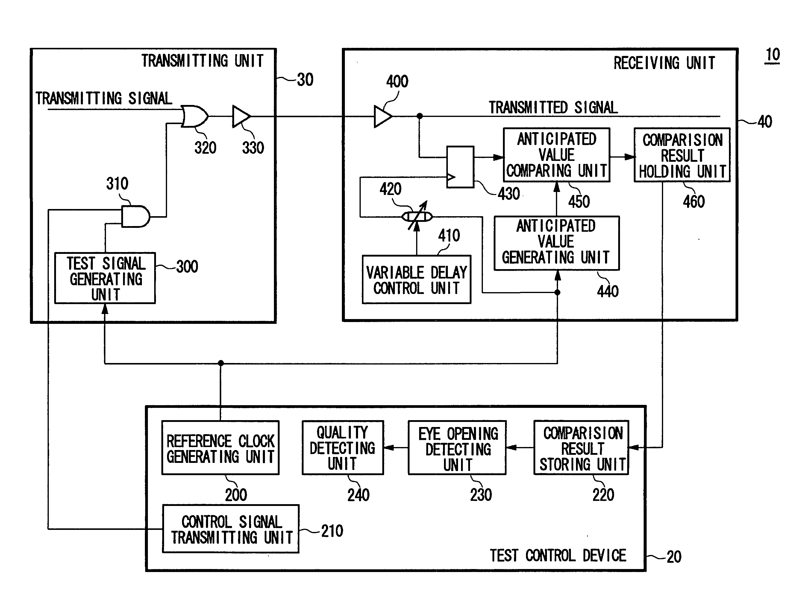
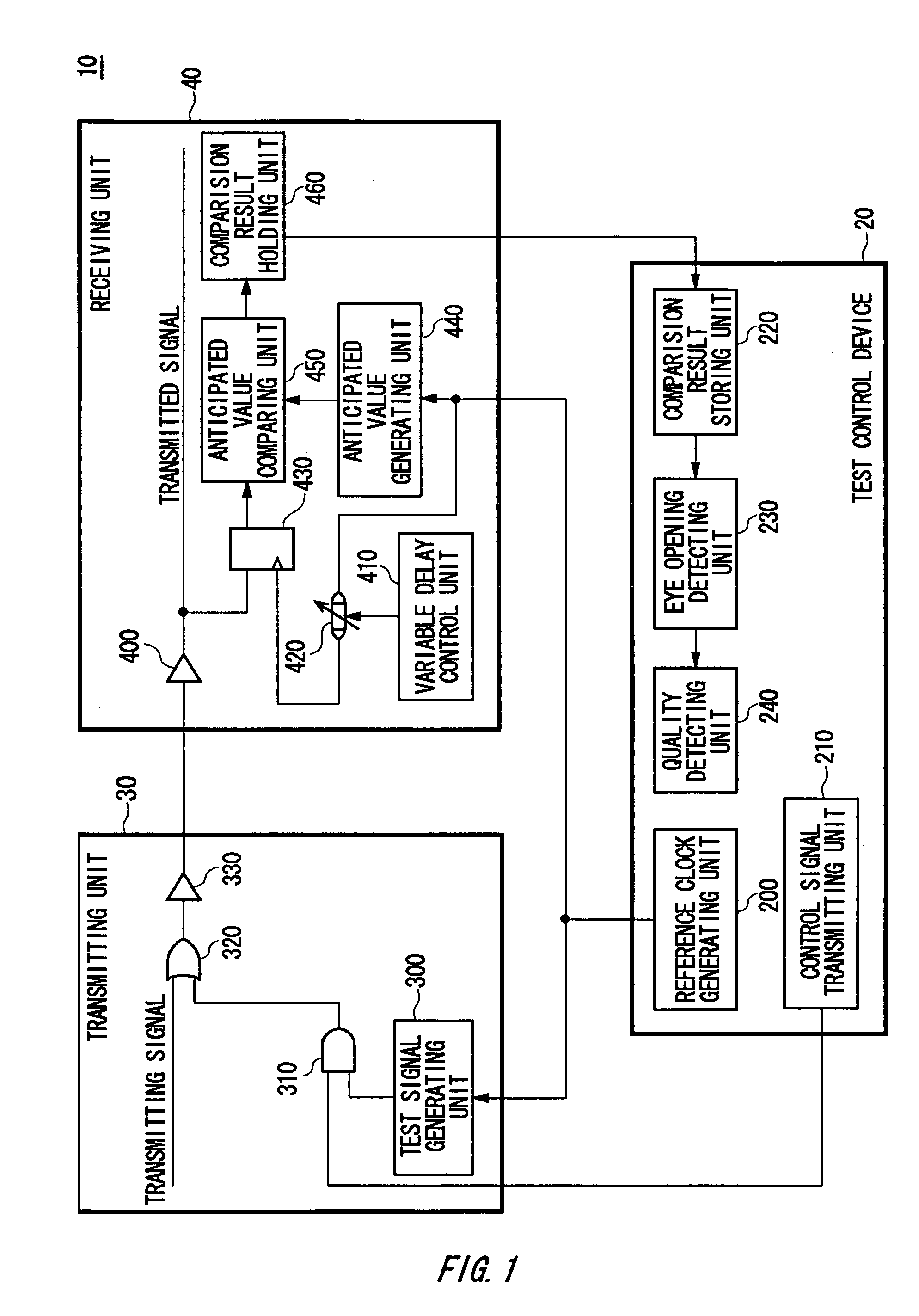
[0027]FIG. 1 illustrates an example of a configuration of a testing system 10 according to a first embodiment of the present invention. It is an object of the testing system 10 according to the present embodiment to perform signal transmission testing at actual operating frequency for communication devices including a transmitting unit 30 and / or receiving unit 40, thereby detecting the eye opening at the actual operating frequency of the communication device in a simulated manner.

[0028] The testing system 10 comprises a transmitting unit 30 for generating and transmitting test signals and a receiving unit 40 for receiving the testing signals which the transmi...


PUM


Abstract

A testing method of a communication device according to the present invention comprises: a step for transmitting and receiving a test signal generated based on a reference clock; a step for generating an anticipated value of the test signal based on the reference clock; a step for delaying the test signal; a step for comparing the delay test signal with the anticipated value and outputting the comparison results; a step for repeatedly performing the above steps and storing the comparison results for each delay time; a step for detecting the eye opening for the test signal based on the comparison results for each delay time; and a step for determining the quality of the communication device based on the detected eye opening.

Description

BACKGROUND OF THE INVENTION [0001] 1. Field of the Invention [0002] The present invention relates to a testing method, a communication device, and a testing system. More particularly, the present invention relates to a testing method for testing communication devices at actual operating frequency. [0003] This application claims the benefit of Japanese Application No. 2003-286040 filed Aug. 4, 2003, and PCT / JP No. 2004 / 10963 filed Jul. 30, 2004, which are hereby incorporated by reference herein in their entirety. [0004] 2. Description of the Related Art [0005] There is a conventionally known testing method for detecting bit errors in signal transmission using a test signal generating unit and an anticipated signal comparing unit built into a communication device, and determining the quality of the communication device. With this testing method, the communication device at the transmitting side generates test signals and transmits to the communication device on the receiving side, and...

Claims


Application Information

Patent Timeline
Patent Type & Authority Applications(United States)
IPC IPC(8): H04J1/16G01R31/28G01R31/30G01R31/3193H04L1/24H04L25/02
CPCG01R31/3016G01R31/31937H04L1/24
Inventor WATANABE, DAISUKE
Owner ADVANTEST CORP
Why Eureka
Try Eureka