Wireless packet communication method and wireless packet communication apparatus

a wireless packet communication and wireless packet technology, applied in the field of wireless packet communication methods and wireless packet communication apparatuses, can solve the problems of large influence of leakage power that leaks from the frequency range of one radio channel to that of another radio channel, difficult to increase throughput, and difficult to achieve the effect of increasing throughpu

Active Publication Date: 2006-09-21
NIPPON TELEGRAPH & TELEPHONE CORP
View PDF35 Cites 29 Cited by
  • Summary
  • Abstract
  • Description
  • Claims
  • Application Information

AI Technical Summary

Problems solved by technology

Therefore, it is difficult to increase the throughput greatly merely by increasing the data transmission rate of a PHY layer.
However, where the center frequencies of the plural radio channels used simultaneously are close to each other, the influence of leakage power that leaks from the frequency range of one radio channel to that of another radio channel is large.
When the transmit-side station attempts to receive this delivery acknowledgment packet, leakage power from another radio channel that is being used simultaneously for transmission is problematic.
As a result, the ACK packet may not be received on radio channel #1 due to leakage power from radio channel #2.
Therefore, as shown in FIG. 21, even if plural data packets are transmitted simultaneously, the packet time lengths of the respective data packets are different from each other and it is highly probable that the reception of an ACK packet fails.

Method used


Image

  • Wireless packet communication method and wireless packet communication apparatus
  • Wireless packet communication method and wireless packet communication apparatus
  • Wireless packet communication method and wireless packet communication apparatus

Examples


first embodiment

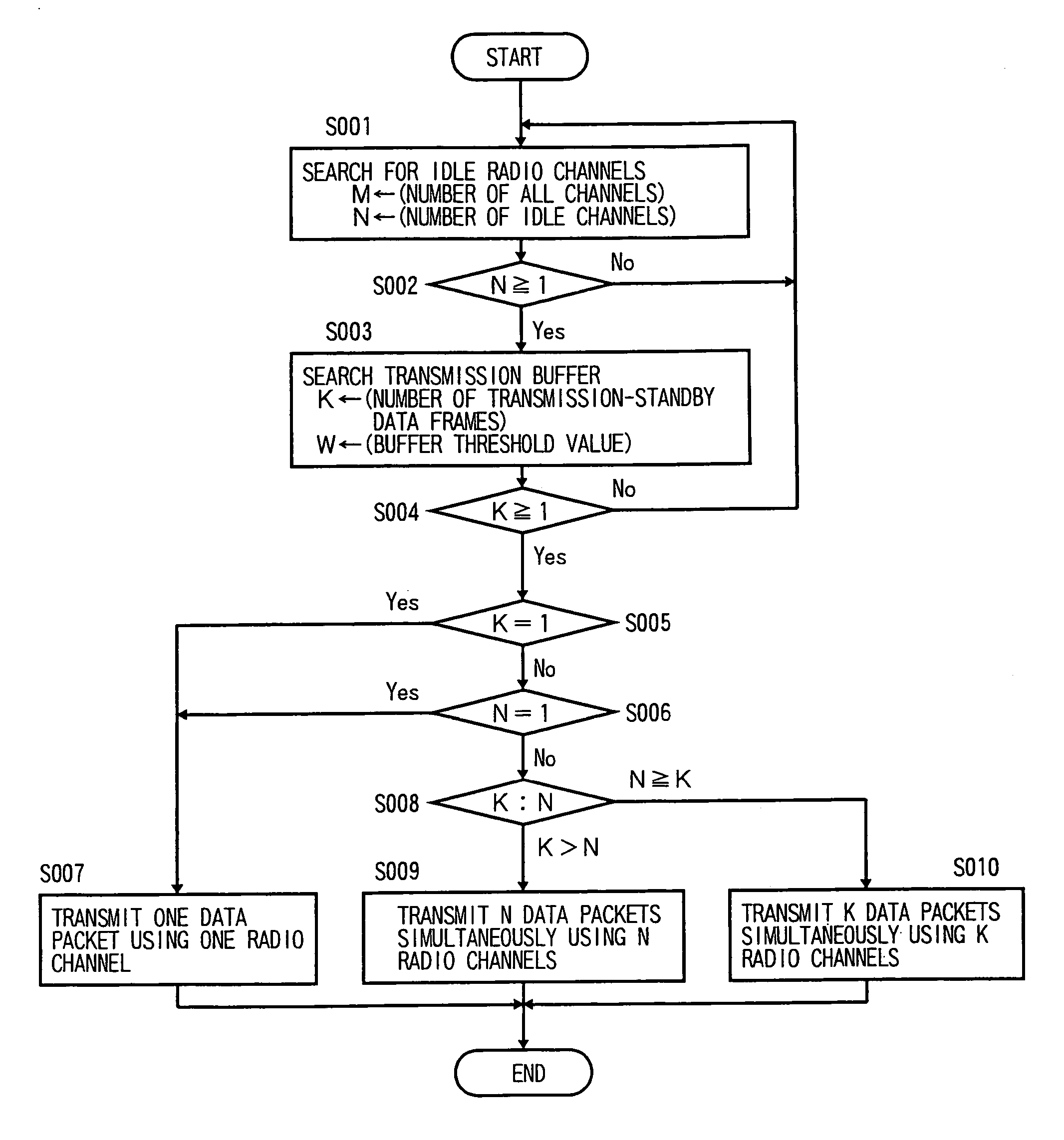
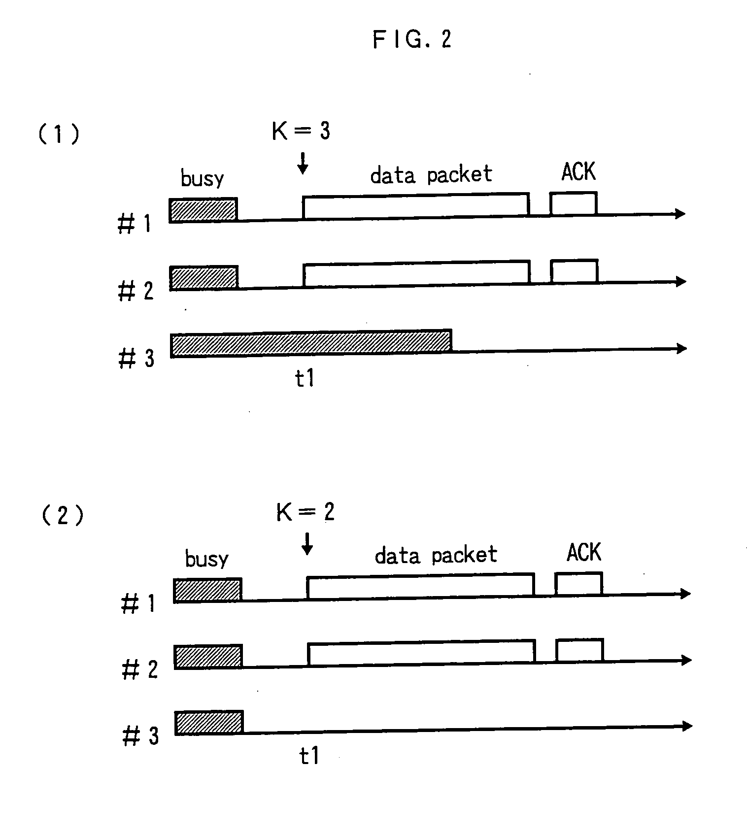
[0061]FIG. 1 is a flowchart showing a first embodiment of the present invention. FIG. 2 shows exemplary operations of the first embodiment of the invention. It is assumed here that radio channels #1, #2, and #3 are prepared between two STAs. The following description will be made with an assumption that transmission-standby data frames in a transmission buffer are to be transmitted between the two STAs and have the same destination.

[0062] Idle radio channels are searched for from all available radio channels by carrier sensing (S001). The number of all channels is represented by M and the number of detected idle channels is represented by N. If one or more idle radio channels are detected, the number K of transmission-standby data frames is acquired by searching the transmission buffer (S002, S003). If no transmission-standby data frame is detected (K=0), the process returns to the carrier sensing. If the number K of transmission-standby data frames is larger than or equal to 1, th...

second embodiment

[0068]FIG. 3 is a flowchart showing a second embodiment of the invention. FIG. 4 shows exemplary operations of the second embodiment of the invention. It is assumed here that radio channels #1, #2, and #3 are prepared between two STAs. The following description will be made with an assumption that transmission-standby data packets in a transmission buffer are to be transmitted between the two STAs and have the same destination.

[0069] An important feature of this embodiment, which differentiates this embodiment from the first embodiment, is to use MIMO. Idle radio channels are searched for from all available radio channels by carrier sensing (S001). The number of all channels is represented by M and the number of detected idle channels is represented by N. If one or more idle radio channels are detected, the sum of MIMO numbers of the respective radio channels is calculated as the number of simultaneous transmissions (S002, S101). For the sake of simplicity, the following descriptio...

third embodiment

[0076]FIG. 5 is a flowchart showing a third embodiment of the invention. FIG. 6 shows exemplary operations of the third embodiment of the invention. It is assumed here that radio channels #1, #2, and #3 are prepared between two STAs. The following description will be made with an assumption that transmission-standby data packets in a transmission buffer are to be transmitted between the two STAs.

[0077] An important feature of this embodiment, which differentiates this embodiment from the second embodiment, is to properly use plural radio channels and MIMO in accordance with the number N of idle channels, the MIMO number L, and the number K of transmission-standby data frames. More specifically, selection is made among a first mode in which a single radio channel is used and MIMO is not used, a second mode in which a single radio channel and MIMO are used, a third mode in which plural radio channels are used and MIMO is not used, and a fourth mode in which plural radio channels and ...


PUM


Abstract

Data packets are transmitted between two STAs capable of using plural radio channels and MIMO together, by using idle channels and MIMO. When at least one idle channel has been detected, plural data packets are generated in the same number as the sum of MIMO numbers of the respective idle channels, in which the data packets are generated from one or plural data frames, and plural data packets having the same packet time length are transmitted simultaneously between the two STAs by using the idle channels and MIMO.

Description

TECHNICAL FIELD [0001] The present invention relates to a wireless packet communication method and a wireless packet communication apparatus for transmitting plural data packets simultaneously between two stations (hereinafter STA) using plural radio channels and / or Multiple Input Multiple Output (hereinafter MIMO). BACKGROUND ART [0002] In conventional wireless packet communication apparatus, only one radio channel to be used is determined in advance, whether this radio channel is idle or not is detected (carrier sense) before transmission of a data packet, and one data packet is transmitted only if the radio channel is idle. This kind of control allows plural STAs to share a single radio channel by using it during periods that are deviated from each other ((1) IEEE802.11 “MAC and PHY Specification for Metropolitan Area Networks,” IEEE802.11, 1998; (2) Low-powered Data Communication System / Broadband Mobile Access Communication System (CSMA) standard, ARIB SDT-T71 version 1.0, Assoc...

Claims


Application Information

Patent Timeline
Patent Type & Authority Applications(United States)
IPC IPC(8): H04L12/413H04J11/00H04J99/00H04W16/02H04W28/00H04W74/08H04W84/12
CPCH04B7/0413H04W74/0808
Inventor NAGATA, KENGO
Owner NIPPON TELEGRAPH & TELEPHONE CORP
Why Eureka
Try Eureka