Image forming apparatus

a technology of image forming apparatus and forming tube, which is applied in the direction of electrographic process apparatus, instruments, optics, etc., can solve the problems of clogging, uniform image quality cannot be obtained, and clogging is especially prone to occur, and achieves uniform image quality and simple configuration.

Inactive Publication Date: 2006-09-21
SEIKO EPSON CORP
View PDF2 Cites 14 Cited by
  • Summary
  • Abstract
  • Description
  • Claims
  • Application Information

AI Technical Summary

Benefits of technology

[0009] It is therefore an object of the invention to provide an image forming apparatus having a simple configuration, in which a carrier liquid is supplied to a development device while the density of a dispersant contained in a carrier liquid stored in a tank is maintained, so that the characteristic of liquid toner is stabilized and a uniform image quality is obtained.
[0010] It is also an object of the invention to provide an image forming apparatus having a simple configuration that can prevent clogging of pipes and valves by toner particles, by employing a liquid toner and a carrier supply cartridge that can easily be detached.

Problems solved by technology

And as a result, as the density of the dispersant in the collected carrier liquid supplied to the development device is changed, the characteristic of the liquid toner, for which the density is controlled, fluctuates, and a uniform image quality can not be obtained.
However, when liquid toner having a thixotropy characteristic and low flowability and high viscosity is employed for a small apparatus in which a limitation is imposed on the diameters of conveying pipes and the layout of the pipes, in some cases, using a pump or a screw to convey this liquid can save substantially more space.
However, when the operation of the apparatus was continued, the following problem was encountered.
That is, toner particles contained in the low viscosity liquid accumulated in the bent portion of the pipe, or in a supply volume adjustment valve, until finally, clogging occurred.
Such clogging especially tends to occur when there is a limitation in the sizes of the pipes and valves provided for a small apparatus (a printer) intended for office use.
Further, unlike regular printers, periodical maintenance is not performed for such small apparatuses, so that clogging can cause a failure.

Method used


Image

  • Image forming apparatus
  • Image forming apparatus
  • Image forming apparatus

Examples


Embodiment Construction

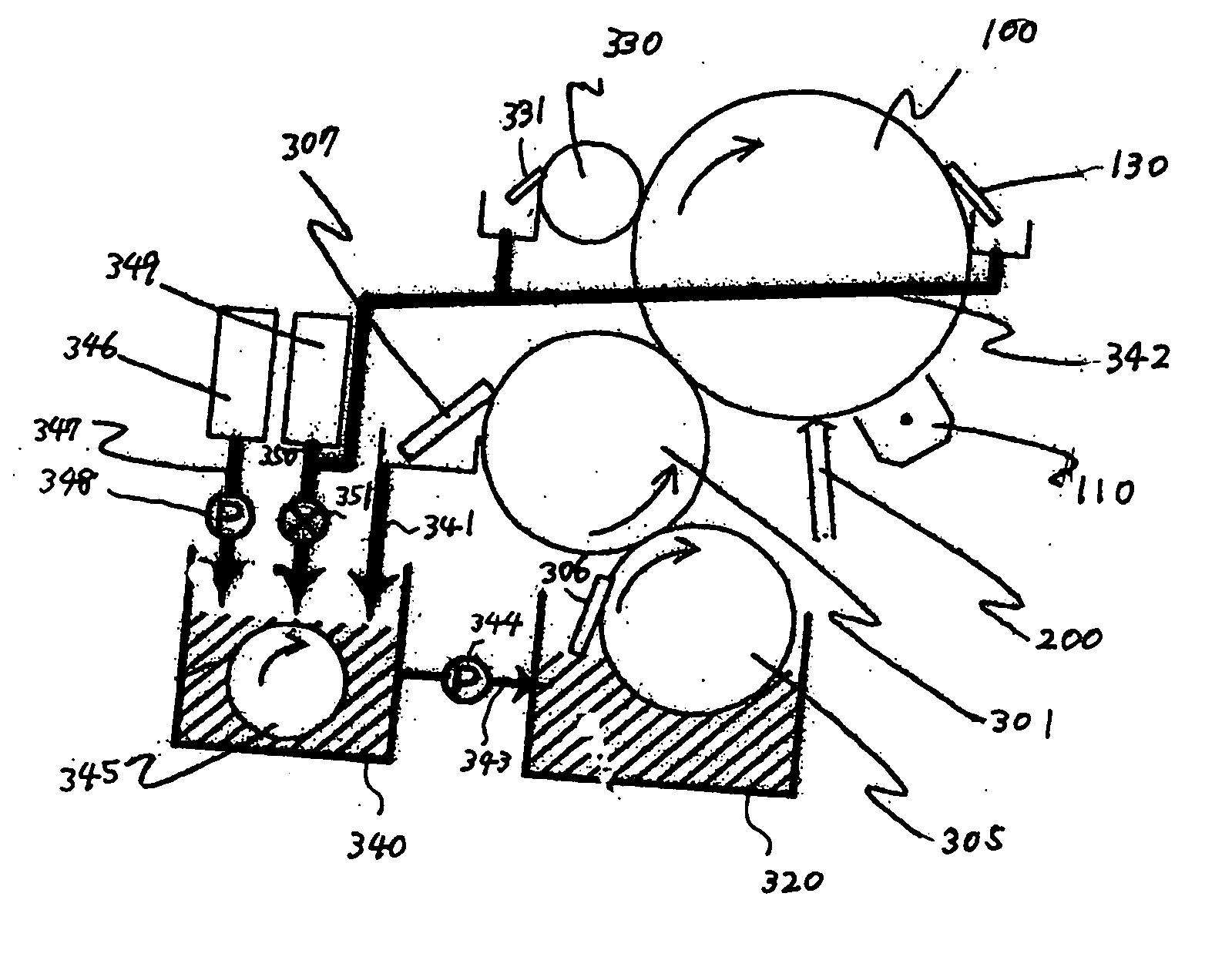
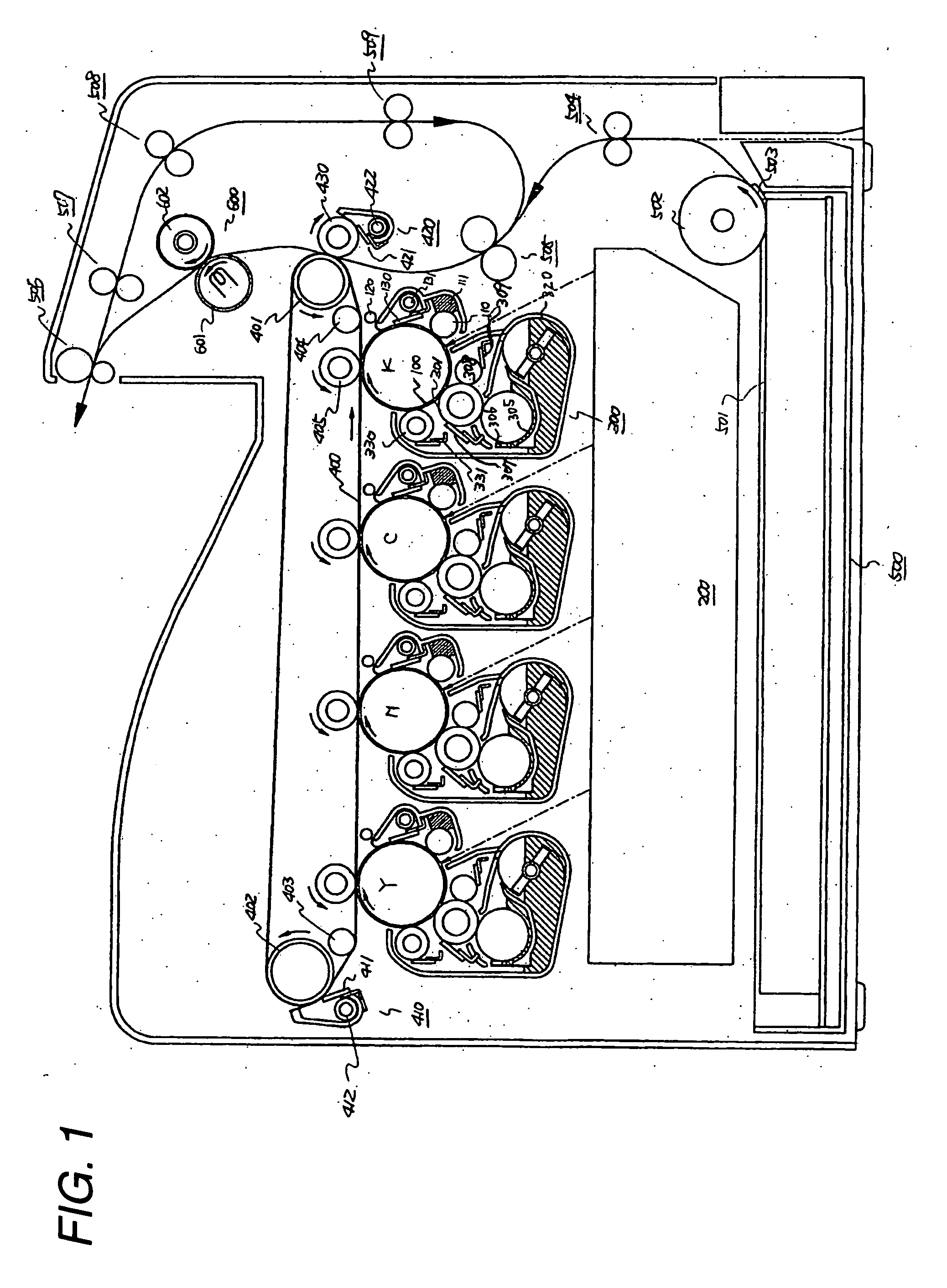
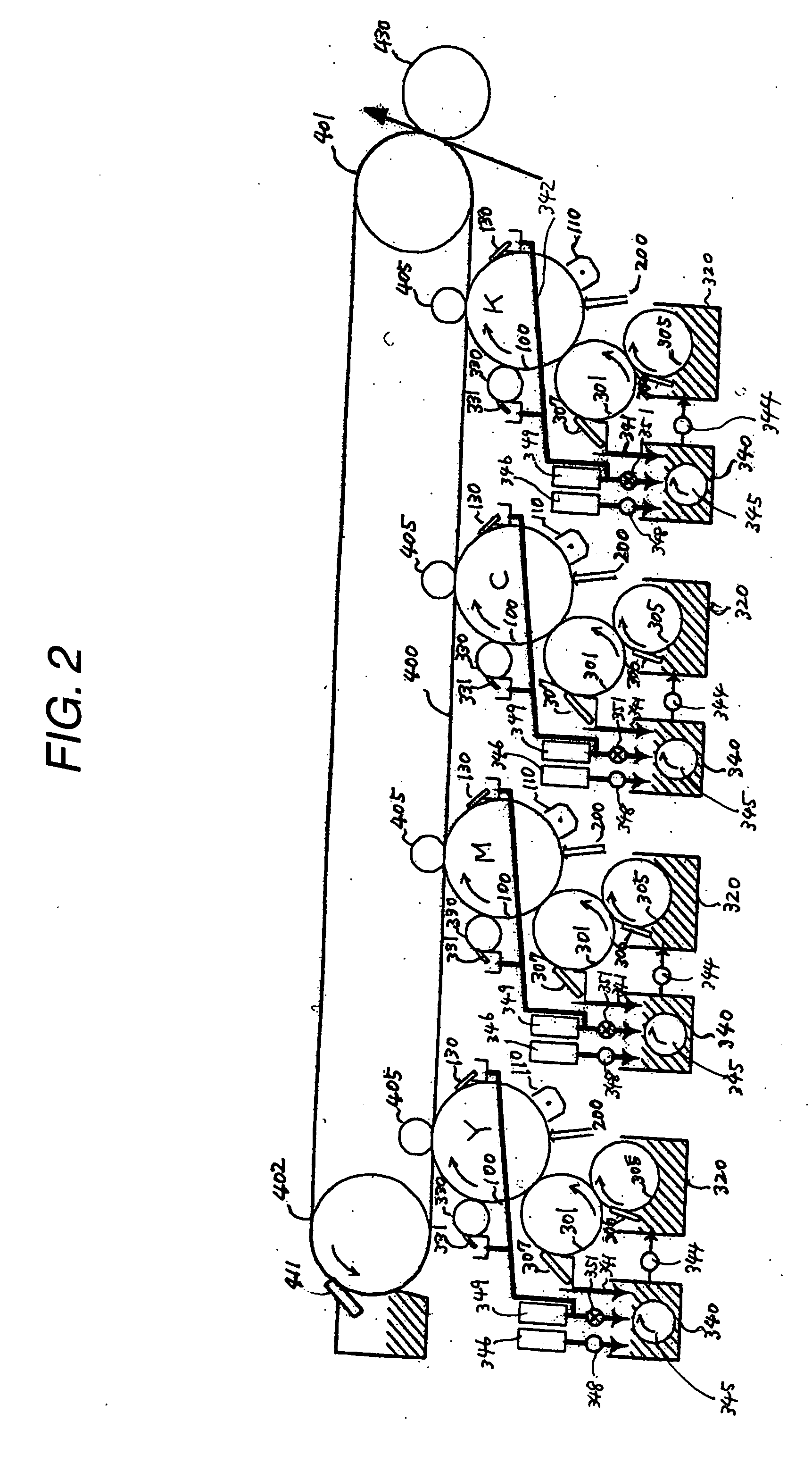
[0052] A first embodiment of the present invention will now be described while referring to the accompanying drawings. FIG. 1 is a diagram showing the general configuration of an image forming apparatus according to the embodiment of the present invention. As shown in FIG. 1, for the image forming apparatus of this embodiment, an intermediate transfer belt 400 is extended and fitted around a drive roller 401, a cleaner backup roller 402 and auxiliary rollers 403 and 404, and below the intermediate transfer belt 400, in a tandem arrangement, are positioned image forming units Y, M, C and K, for the colors yellow, magenta, cyan and black.

[0053] The image forming processing performed by the image forming apparatus of this embodiment will now be explained by employing the black image forming unit K. Since the yellow, magenta and cyan image forming units, Y, M and C, have the same arrangements, no further explanation for them will be given.

[0054] The surface of a photoreceptor 100, whi...


PUM


Abstract

An image forming apparatus includes a developing section in which an image is developed by using liquid toner. The liquid toner has passed through the developing section is conveyed in a first path by gravity. A tank is adapted to store a carrier liquid, and is connected to a second path in which the carrier liquid stored in the tank is conveyed by gravity and which joins the first path.

Description

BACKGROUND OF THE INVENTION [0001] The present invention relates to an image forming apparatus for developing an electrostatic latent image, formed on a photoreceptor, by employing a liquid toner prepared by dispersing toner particles in a carrier liquid. [0002] Related image forming apparatuses are known that develop electrostatic latent images by employing liquid toner prepared by dispersing toner particles in a carrier liquid. Also known, for such image forming apparatuses, are arts for collecting and recycling the liquid toner. [0003] One image forming apparatus that employs a liquid toner to develop an electrostatic latent image is disclosed in JP-A-10-282796. According to JP-A-10-282796, liquid toner that is not used during development is collected, and after having been separated into high-density liquid and into either carrier liquid or low-density liquid, is stored separately, in appropriate containers. Subsequently, these liquids are mixed together to obtain an adjusted, p...

Claims


Application Information

Patent Timeline
Patent Type & Authority Applications(United States)
IPC IPC(8): G03G15/10
CPCG03G15/104
Inventor NAKAMURA, MASAHIDETAKANO, HIDEHIROKAMIJO, KOICHIIKUMA, KEN
Owner SEIKO EPSON CORP
Why Eureka
Try Eureka