

Food container particularly for forming a party platter or the like
- Summary
- Abstract
- Description
- Claims
- Application Information
AI Technical Summary
Benefits of technology
Problems solved by technology
Method used
Image

Examples
second embodiment
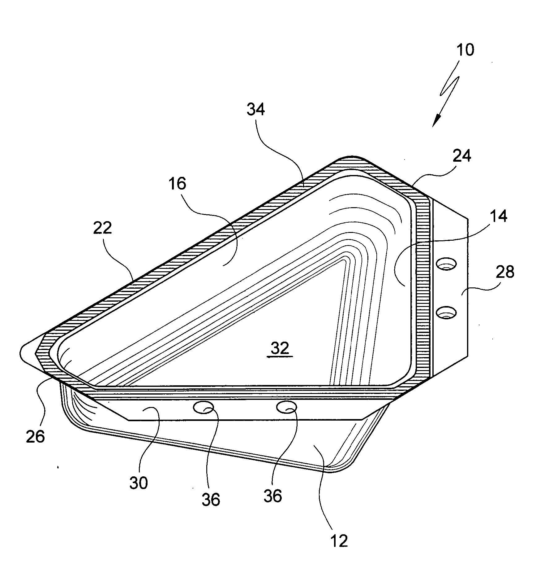
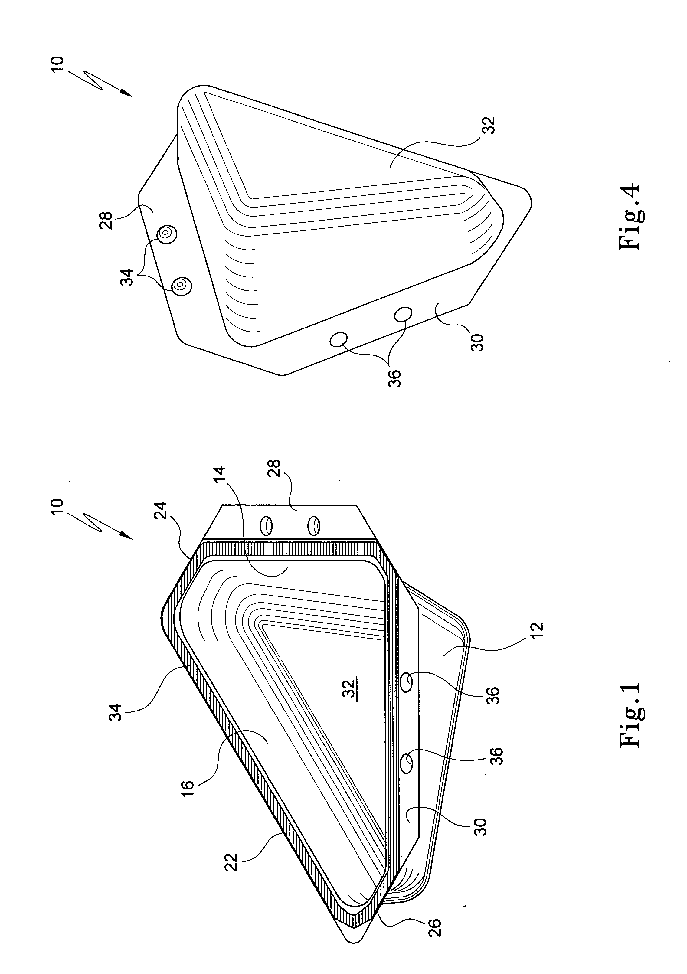
[0066] FIGS. 6 to 8 show a container 110. The container has a generally flat base 111 . With reference to FIG. 7, the container defines a relatively longer arcuate outer wall 112 and a relatively shorter, but concentric, arcuate inner wall 114. The radius of the outer wall is 200 mm and that of the inner wall is 55 mm although these dimensions could be varied. The ends of the arcuate walls are connected by two radially extending straight side walls 116 and 118. The. angle γ subtended by the two side walls is 60°.
[0067] In the specific example shown, the outer wall 114 has a height h1 of 70 millimetres, and the inner wall a height h2 of 20 millimetres from the base 111 to its top 120. Also as can be best seen in FIG. 8, the outer wall 112, is extends way from the container at an angle of about 110 to 120° rather than being perpendicular to the base 111.
[0068] An external flange 122, extends around the perimeter of the top 120 of the container. As shown in FIG. 7, the plane flange is...
third embodiment
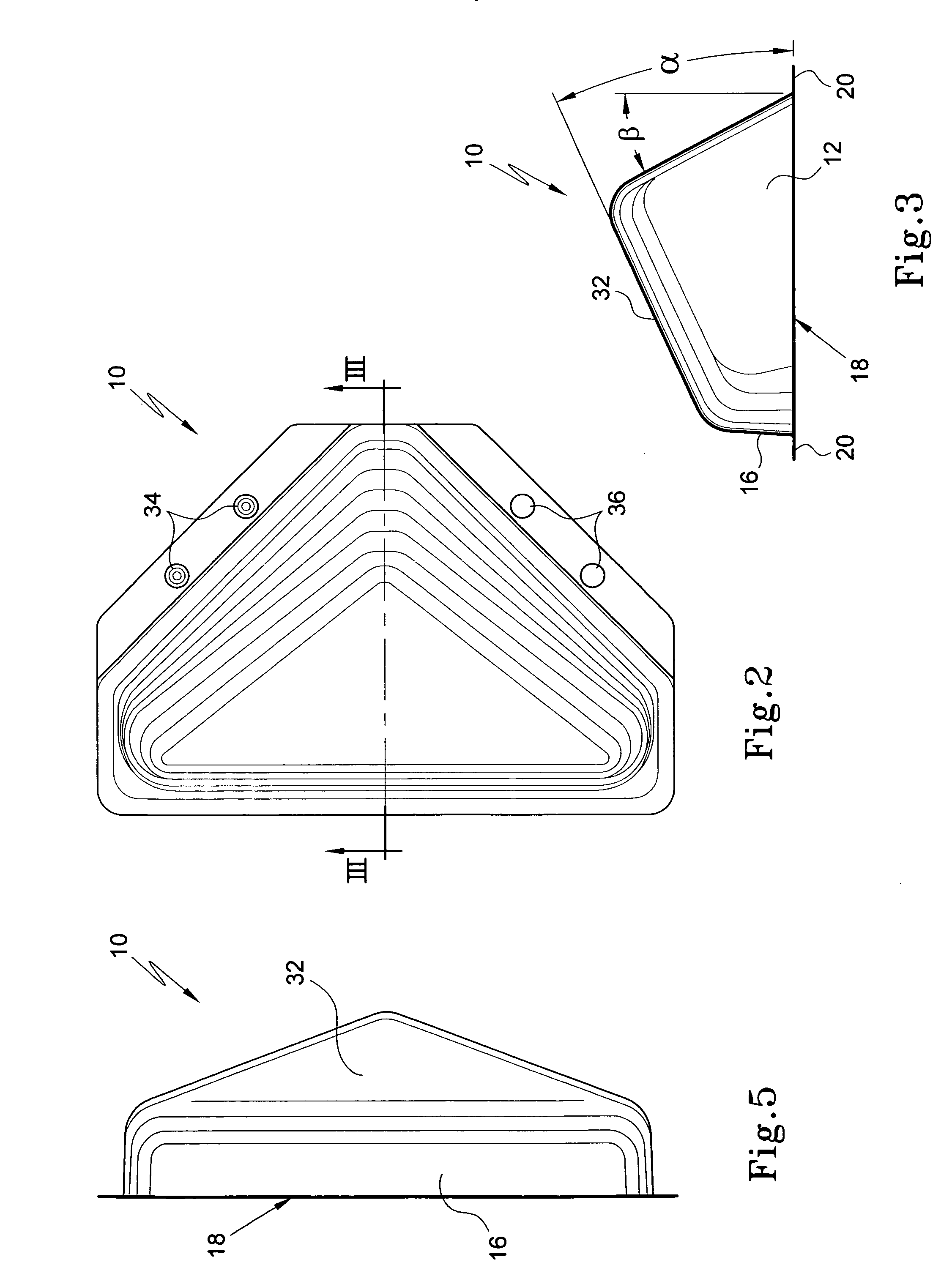
[0072]FIG. 12 is a pictorial view of a four containers 10A of the invention. The containers are essentially identical to that shown in FIGS. 1 to 5 except that the interlocking means comprise smaller and larger interlocking lugs as described above in relation to the embodiment of FIG. 6 to 8 rather than lugs and holes. Four such containers are shown partially assembled into a platter.
fourth embodiment
[0073]FIG. 13 is a pictorial view of six containers 110A according to the invention. The containers are substantially identical to the embodiment of FIGS. 6 to 8 except that the external edge of the flange 122 is straight rather than curved. The containers are shown formed in plastic and assembled into a platter.
[0074]FIGS. 15 and 16 show a yet further embodiment of a food container 300. The container 300 is similar to that shown in FIGS. 6 to 8 except that the outer wall 312 is straight rather than arcuate. In all other respects the containers are the same and in particular container 300 includes an external flange 322 projecting from the top edge of the container with the flanges on respective side walls of the container defining a series of depending lugs 319 and 321, for use in interlocking like containers together, FIG. 16 shows a hexagonal platter 320 which has been assembled from six such containers.
[0075] FIGS. 17 to 19 illustrates a yet further embodiment of a container wh...
PUM
 Abstract
Description
Claims
Application Information