Process and installation for the fractionation of air into specific gases

a technology for separating air and specific gases, applied in separation processes, hydrogen sulfides, lighting and heating apparatus, etc., can solve the problems of many existing installed units may face operation problems, and the drawback of necessitating large and expensive pressure vessels, etc., to achieve the effect of improving the conversion performan

Inactive Publication Date: 2006-09-28
CO2 SOLUTION
View PDF11 Cites 44 Cited by
  • Summary
  • Abstract
  • Description
  • Claims
  • Application Information

AI Technical Summary

Benefits of technology

The invention is about a method to recycle an ion-rich solution back into CO2. This can be done using a regenerator or percolation cooling tower that has a biocatalyst to improve its performance. The technical effect of this invention is to provide a more efficient way to recycle and reuse resources.

Problems solved by technology

The technical problem addressed in this patent text is the need for a more efficient and less costly process and apparatus for the production of oxygen and/or nitrogen by air distillation, as current methods require large and expensive equipment and high energy input to remove carbon dioxide and water from the air. Additionally, the increasing carbon dioxide concentration in atmospheric air may limit the operation of existing units.

Method used


Image

  • Process and installation for the fractionation of air into specific gases
  • Process and installation for the fractionation of air into specific gases
  • Process and installation for the fractionation of air into specific gases

Examples


Embodiment Construction

[0028] Preferred embodiments of the installation and process will be described hereafter.

[0029] The invention provides an installation and a process that enable air containing CO2 to be treated in order to reduce the amount of CO2 contained therein while substantially improving the efficiency of fractioning the air into various sub-components, more namely into nitrogen and oxygen.

The installation

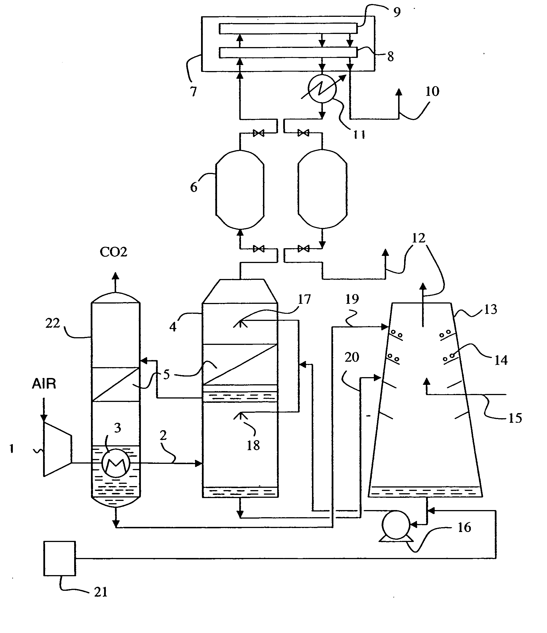
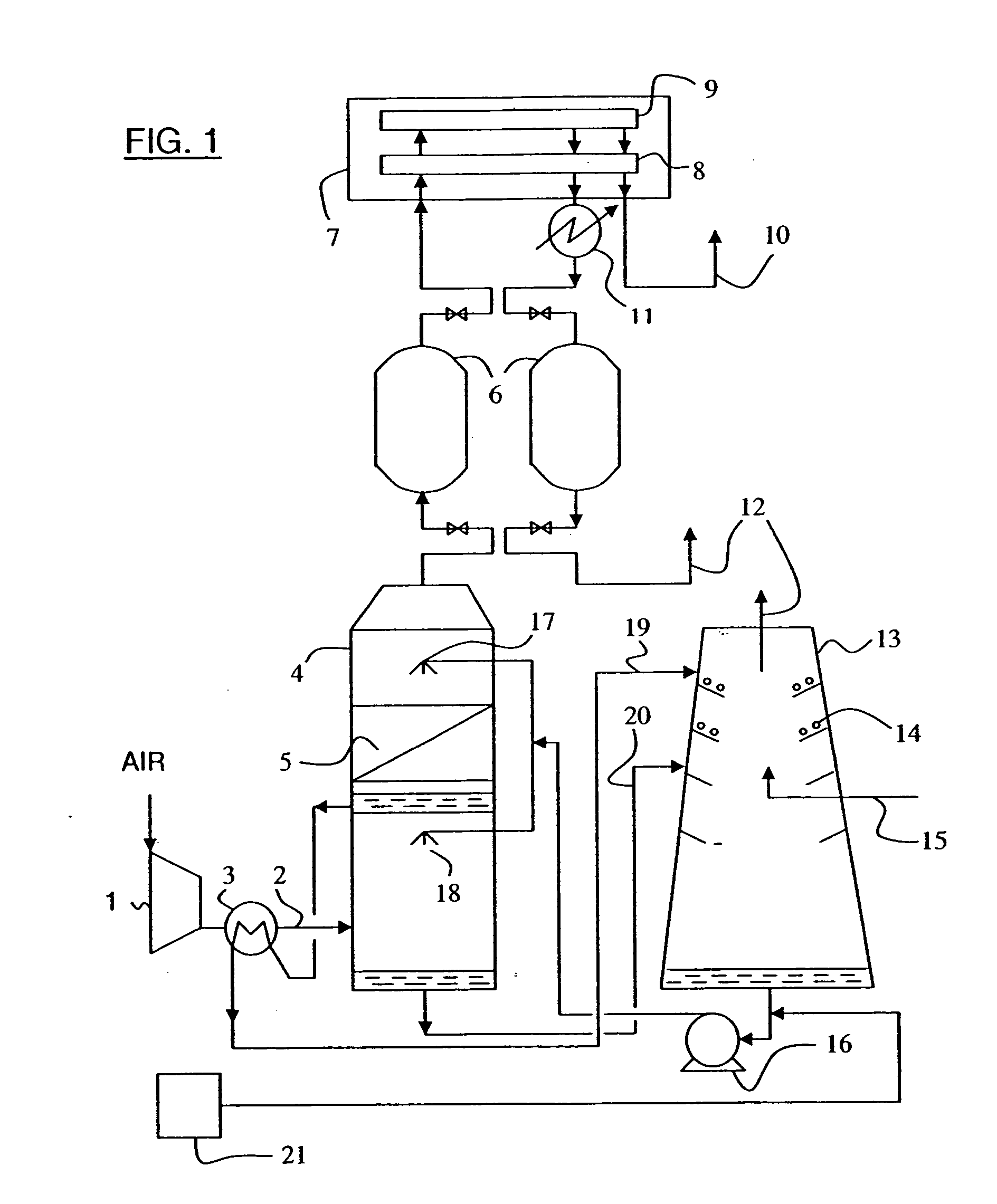
[0030] The installation shown in FIG. 1 is preferably used in a variety of production facilities, for producing oxygen and / or nitrogen by fractioning air and / or another gas containing CO2.

Equipment for Producing the Air to be Treated

[0031] The installation shown in FIG. 1 includes a principal air compressor 1 in the discharge 2 of which is mounted a heat exchanger 3. The compressed air is often hot when fed to the spray tower, and in preferred embodiments has a temperature of about 80° C. However, the compressed air may also be provided at numerous other temperatures.

Spray Tower

[00...


PUM

PropertyMeasurementUnit
Pressureaaaaaaaaaa

Abstract

In order to reduce incoming atmospheric carbon dioxide levels in compressed air prior to cryogenic distillation, a water spray cooling tower equipped with biocatalytic packing, or fed with absorptive reagents, is used to convert gaseous carbon dioxide into bicarbonate ions which dissolve in the cooling water. The hydration reaction and refrigeration occur synergistically. The bicarbonate ions are subsequently removed from the solution using the heat from the compressed air in a regenerator re-boiler unit, and then fed to a percolation cooling tower for releasing CO2 and cooling.

Description


Claims


Application Information

Patent Timeline
Owner CO2 SOLUTION
Why Eureka
Try Eureka