Laminating unit

a technology of laminated units and laminated sheets, applied in the field of laminated sheets, can solve the problems and achieve the effect of freeing up a considerable amount of spa

Inactive Publication Date: 2006-09-28
LOIBL BERND
View PDF1 Cites 6 Cited by
  • Summary
  • Abstract
  • Description
  • Claims
  • Application Information

AI Technical Summary

Benefits of technology

[0008] This object is achieved, according to the present invention, in that the insertion opening of the feedthrough conduit is located on the back side of the housing, and the exit opening on the front side, i.e. transport of the combination of sheet material and films occurs from the back side to the front side, and thus in the opposite way from laminating units of the existing art. Because of this reversal of the feedthrough direction, it is possible to position the laminating unit with its back side at the edge of a desktop, thereby freeing up a considerable amount of space. The sheet material emerging from the exit opening on the front side is then not subject to the risk of dropping to the floor, since it drops onto the desktop and can therefore be immediately picked up by the operator.

Problems solved by technology

Because of this reversal of the feedthrough direction, it is possible to position the laminating unit with its back side at the edge of a desktop, thereby freeing up a considerable amount of space.

Method used


Image

  • Laminating unit
  • Laminating unit
  • Laminating unit

Examples


Embodiment Construction

)

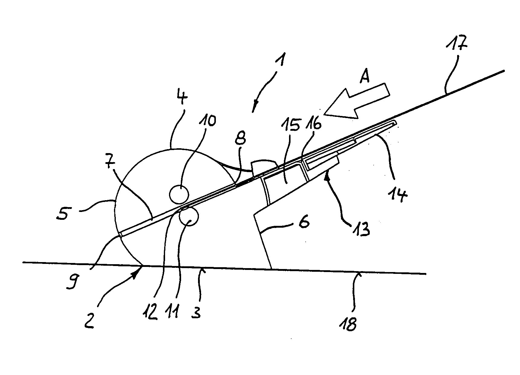
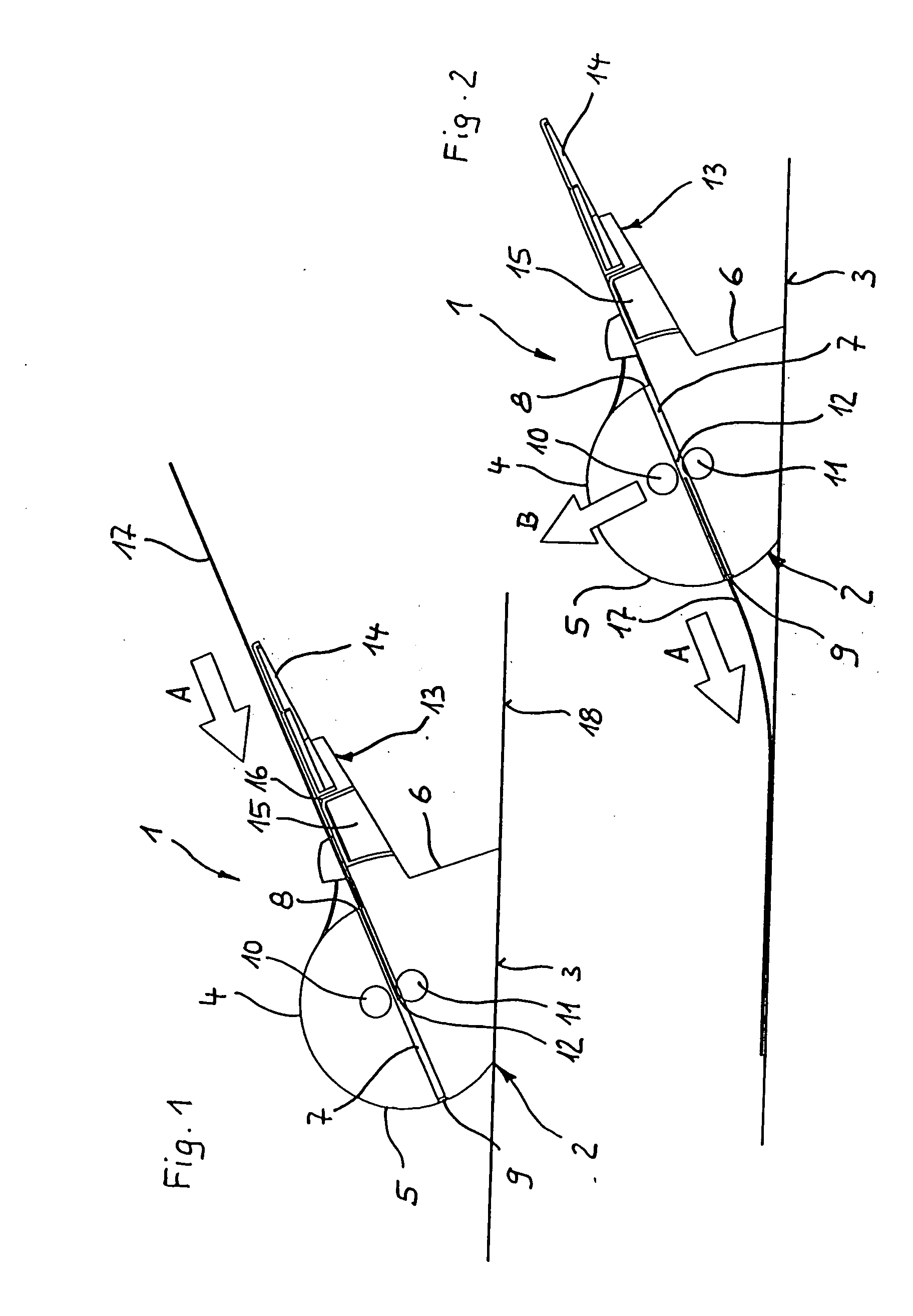
[0016] Laminating unit 1 depicted in FIGS. 1 and 2 has a housing 2 having a flat housing base 3 and a semi-cylindrical housing superstructure 4 that continues toward the rear in straight and oblique fashion into housing base 3. In the cross section shown, housing superstructure 4 extends perpendicular to the drawing plane and is delimited on both sides by flat sidewalls. Housing superstructure 4 forms a rounded front side 5 and a back side 6.

[0017] Extending through housing 2 from back side 6 to front side 5 is a downwardly directed feedthrough conduit 7, not very high and having a width such that DIN A4 sheet material can be fed through in landscape format. Feedthrough conduit 7 is delimited at one end by an insertion opening 8 at back side 6, and by an exit opening 9 at front side 5.

[0018] In feedthrough conduit 7 are two laminating rollers 10, 11 that are arranged one above another and form between them a laminating gap 12 that extends over the width of feedthrough conduit 7. ...


PUM

PropertyMeasurementUnit
transparentaaaaaaaaaa
transparencyaaaaaaaaaa
widthaaaaaaaaaa

Abstract

A laminating unit for laminating sheet material to at least one film has a housing that comprises a front side and a back side. A feedthrough conduit extends between the front and back sides and has an insertion opening for the introduction of sheet material and film(s) and an exit opening for ejection of the laminated combination of sheet material and films(s). A laminating device for laminating the sheet material and for transporting the combination of sheet material and film(s) to the exit opening during lamination is provided in the housing. The insertion opening is located on the back side of the housing and the exit opening on the front side.

Description

CROSS-REFERENCE TO RELATED APPLICATIONS AND CLAIM TO PRIORITY [0001] This application is based upon utility model application number 20 2005 005 020.2, filed Mar. 24, 2005 in the Federal Republic of Germany, the disclosure of which is incorporated herein by reference and to which priority is claimed. FIELD OF THE INVENTION [0002] The invention concerns a laminating unit for laminating sheet material to at least one film, having a housing that comprises a front side and a back side and a feedthrough conduit, extending between the front and back sides, that has an insertion opening for the introduction of sheet material and film(s) and an exit opening for ejection of the laminated sheet material, a laminating device for laminating the sheet material and for transporting the combination of sheet material and film(s) during lamination from the insertion opening to the exit opening being provided in the housing. BACKGROUND OF THE INVENTION [0003] Laminating units are used in offices to e...

Claims


Application Information

Patent Timeline
Patent Type & Authority Applications(United States)
IPC IPC(8): B32B37/00B32B37/14B32B37/18B32B39/00B65H39/14
CPCB32B37/142B32B37/185B32B39/00B32B2037/0061Y10T156/17B65H39/14B65H2301/5114Y10T156/1744B32B2425/00
Inventor LOIBL, BERND
Owner LOIBL BERND
Why Eureka
Try Eureka