ARC chute assembly and electric power switch incorporating same

Inactive Publication Date: 2006-09-28
EATON CORP
9 Cites 13 Cited by

AI-Extracted Technical Summary

Problems solved by technology

Arc splitting into series arcs also results in increased arc voltage due to additional cathode fall potential.
Many circuit breakers, especially molded case circuit breakers due to their small size and cable location adjacent to the arc chute, limit effective gas flow out of the breaker....

Benefits of technology

[0008] This need and others are satisfied by the invention which is directed to facilitating the exhaustion of ...

Abstract

As many as possible of the arc plates of an arc chute assembly have complimentary reverse compound curves to form between them gas flow paths for arc gas that discharge directly into a gas vent. Where the gas vent is not large enough, the remaining arc plates have a concave upward curvature forming additional gas flow paths that discharge smoothly into a vertical gas passage adjacent their trailing edges that extends upward to the gas vent.

Application Domain

High-tension/heavy-dress switchesAir-break switches

Technology Topic

Trailing edgeElectric arc +2

Image

  • ARC chute assembly and electric power switch incorporating same
  • ARC chute assembly and electric power switch incorporating same
  • ARC chute assembly and electric power switch incorporating same

Examples

  • Experimental program(1)

Example

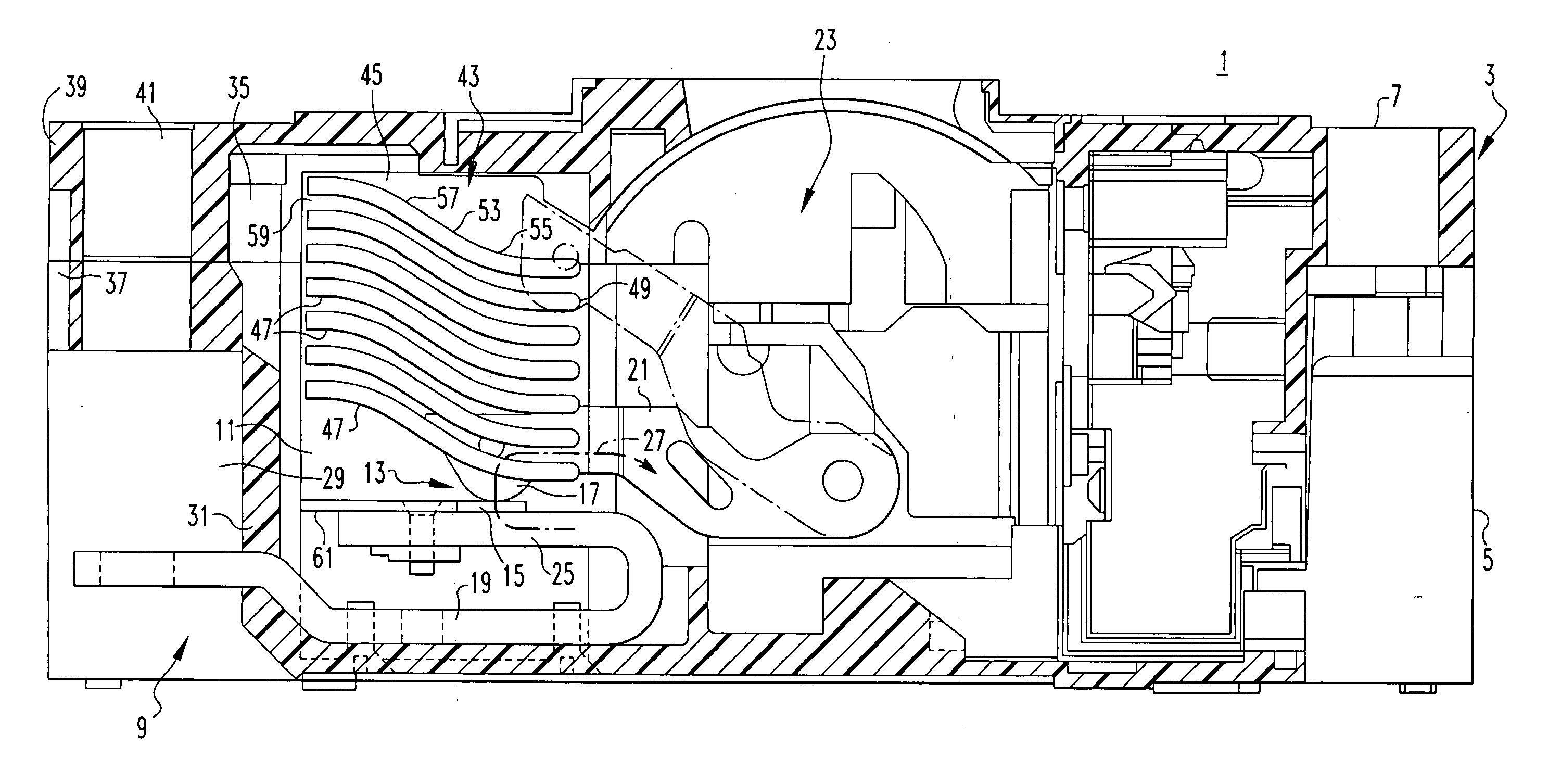
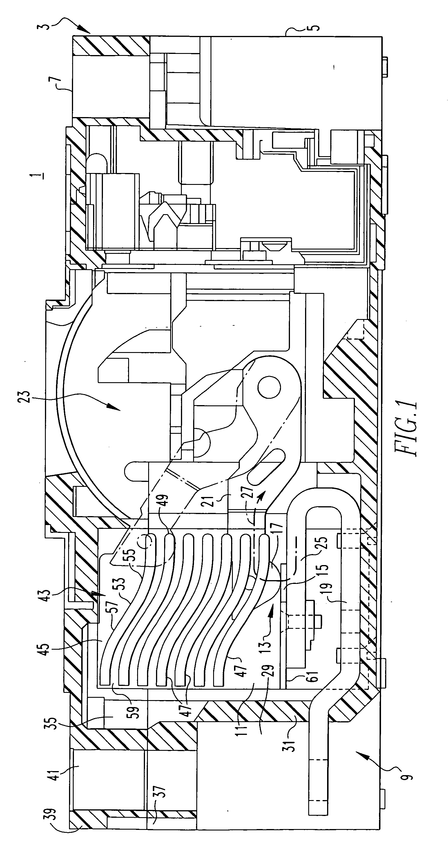
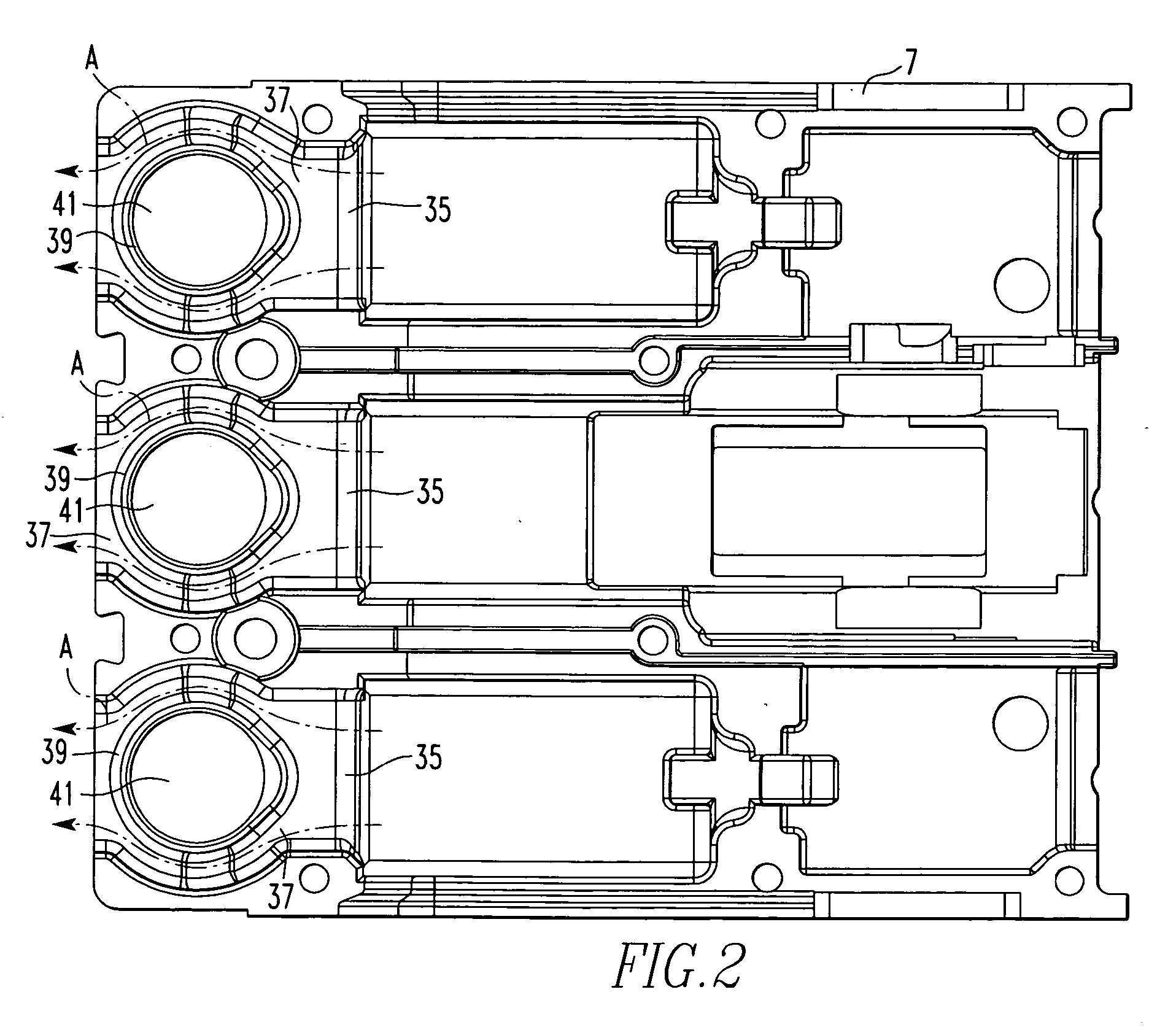
[0017] The invention will be described as applied to a molded case circuit breaker, however, it will be apparent that the invention has application to other types of electric power switches in which the contacts are separated in an ambient atmosphere. The molded case circuit breaker 1 has a casing 3 formed by a base 5 and a cover 7. The particular circuit breaker 1 is a three-pole breaker. Accordingly, the casing 3 has for each pole 9 an arc chamber 11 containing separable contacts 13 including a fixed contact 15 and a movable contact 17. The fixed contact 15 is mounted on a line side main conductor 19 while the movable contact 17 is mounted on the free end of a pivotally mounted contact arm 21. The contact arms 21 of all of the poles 9 are simultaneously rotated from a closed position in which the separable contacts 13 are closed as shown in FIG. 1 to an open position (shown in phantom) by an operating mechanism 23 in a well-known manner. The line side main conductor 19 is bent back upon itself at 25 so that current in this bent section 25 forms with the current flowing in the opposite direction through the movable contact arm 21 a reverse current loop 27 to generate magnetic repulsion forces that aid in rapid opening of the separable contacts 13 in response to high overcurrent, again as is well known.
[0018] The circuit breaker 1 has for each pole 9 an external terminal recess 29 that is separated from the corresponding arc chamber 11 by a vent wall 31 formed by the casing 3. The line side main conductor 19 extends from the fixed contact 15 through the vent wall 31 into the corresponding external terminal recess 29. A terminal assembly (not shown) in each terminal recess 29 connects the line side main conductor 19 of the pole 9 to an external conductor (also not shown).
[0019] The vent wall 31 has a gas vent 35 in an upper portion above the terminal recess through which arc gas generated during opening of the separable contacts 13 is vented from the arc chamber 11. This gas vent 35 connects with the atmosphere through a passage 37 that extends around a protrusion 39 molded on the cover 7 that forms an opening 41 through which a tool can be inserted to manipulate a terminal assembly in the terminal recess 29. The arc gases escaping through the gas vent 35 flow through the passage 37 around this protrusion 39 as shown by the arrows A in the bottom plan view of the cover 7 shown in FIG. 2. In the embodiment of FIG. 1, the external terminal recess 29 extends only part way up the base 5 of the casing 3 so that the protrusion 39 and the passage 37 extend downward into the upper part of the base 5 making possible a longer gas vent 35.
[0020] Returning to FIG. 1, an arc chute assembly 43 is provided in the arc chamber 11 between the separable contacts 13 and the gas vent 37. The arc chute assembly 43 includes a supporting structure such as a molded housing or flat side plate 45 that supports a plurality of arc plates 47 in spaced relation. Each of the arc plates 47 has a leading edge 49 adjacent the separable contacts 13 and a trailing edge 51 facing the gas vent 35. Each of the arc plates 47 also has a reverse compound curvature 53. By reverse compound curvature 53 it is meant that each plate 47 has a first curvature 55 extending generally laterally away from the leading edge and upward and a second curvature 57 that extends generally laterally from the trailing edge and downward. In the exemplary embodiment, the second curvature leads directly into the first curvature so that there is a continuous but reversing curvature between the first curvature and the second curvature. Together the first and second curvatures form arc plates 47 that are concave upward adjacent the leading edge and convex upward adjacent the trailing edge.
[0021] Adjacent arc plates 47 with their reverse compound curvatures 53 form between them gas flow paths 59 that are generally aligned with and discharge directly into the gas vent 35. The reverse compound curvatures of adjacent arc plates 47 are complementary so that adjacent arc plates 47 are equally spaced from leading edge to trailing edge. This provides a smooth flow of gas to the gas vent 35. It is not necessary that the adjacent arc plates 47 be equally spaced throughout their lengths as long as there are no discontinuities including where the gas flow path discharges into the gas vent 35 so that the gas flow is laminar to enhance the escape of the gas and improve cooling of the arc. As is conventional, an arc runner 61 extending from adjacent the fixed contact 15 guides the arc into the arc plates 47.
[0022]FIG. 3 illustrates another embodiment of the invention where the height of the gas vent 35′ is limited such as by the height of the external terminal recess 29′. In this case, a selected number 63 of the arc plates 47 at the top of the stack have the reverse compound curvature 53 that form the gas flow paths 59 that discharge directly into the gas vent 35′. The others of the arc plates 47′ below these arc plates 47 with the reverse compound curvature 53 have a single curvature 65 that makes them concave upward in the direction of the gas vent 35′ with their trailing edges 51 above their leading edges 49. These arc plates 47′ form additional gas flow paths 59′ that extend upward and discharge upward toward the gas vent 35′ into a vertical gas passage 67 between the vent wall 31′ and the trailing edges 51 of the arc plates 47′. As opposed to prior art arc chute assemblies in which the arc gases flowing between the lower arc plates discharge into such a gas passage with a large component perpendicular to the vent wall causing back pressure on the gases, the additional gas flow paths 59′ direct the gas smoothly into the gas passage 67 with negligible turbulence.
[0023] While specific embodiments of the invention have been described in detail, it will be appreciated by those skilled in the art that various modifications and alternatives to those details could be developed in light of the overall teachings of the disclosure. Accordingly, the particular arrangements disclosed are meant to be illustrative only and not limiting as to the scope of the invention which is to be given the full breadth of the claims appended and any and all equivalents thereof.

PUM

no PUM

Description & Claims & Application Information

We can also present the details of the Description, Claims and Application information to help users get a comprehensive understanding of the technical details of the patent, such as background art, summary of invention, brief description of drawings, description of embodiments, and other original content. On the other hand, users can also determine the specific scope of protection of the technology through the list of claims; as well as understand the changes in the life cycle of the technology with the presentation of the patent timeline. Login to view more.

Similar technology patents

Dual camera digital video comparator for forensic evidence

InactiveUS20140028853A1improve capability
Owner:BENNETT DYER M +2

Method for manufacturing electrode material and electrode material

ActiveUS20170282249A1improve capability
Owner:MEIDENSHA ELECTRIC MFG CO LTD

Chimney

InactiveUS20130109287A1lower resistanceimprove capability
Owner:ZHENG DEMING

Systems and Methods for Awareness in Vehicles Using Haptic Effects

ActiveUS20180056867A1improve capabilityincrease awareness
Owner:IMMERSION CORPORATION

Polymer composition containing a phosphonate flame retardant

PendingUS20210309831A1improve capabilityprevent decomposition
Owner:CHEM FAB BUDENHEIM AG

Classification and recommendation of technical efficacy words

  • improve capability

Blender base with food processor capabilities

InactiveUS20070201306A1improve capabilityeasily detach
Owner:SUNBEAN PROD INC

Cement composition

InactiveUS20050016421A1improve capabilityenhanced strength
Owner:NAT AGRI & FOOD RES ORG +1

Method for error-correction coding

InactiveUS20180248567A1improve capability
Owner:HUAZHONG UNIV OF SCI & TECH

High protein content food supplement

InactiveUS20050129835A1improve capabilityeasily add
Owner:DELAHANTY DONALD W JR
Why Eureka
Try Eureka